Basins in Roman aqueducts
HOME
In Roman times the water, on its way between source and city, would have passed bridges, tunnels and/or arcades, but also basins with specific functions
some of them even with more than one function. Apart from the well known distribution basins (castellum aquae), some basins were made for collecting,
for cleaning or to decrease in the velocity of the water flow.
The terminology of the different types of basins is confusing. The scheme given below may act as a guide to understand the function of each basin.
|
For drawings and photo's, see subsite
|
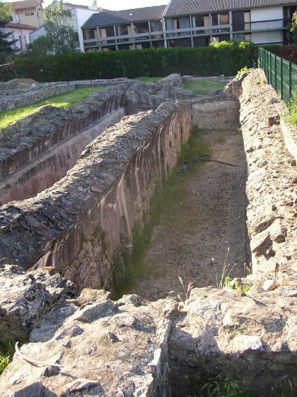
1. Storage basin
It purpose was to store aqueduct water in order to absorb fluctuations in the water supply and discharge. The photo shows a multiple chamber basin with
conneting corridors and a drain (not visible) on the La Fourvičre hill in Lyon (France); the visible chambers are both lower ones of a four chamber basin.
A Roman cistern is often related to a basin to store rainwater. It was part of the 'standard' Roman house and found under the implusium.
Cisters were (and still are) common in very arid areas with long dry seasons.
2. Distribution basin
In classical as well as in modern literature the distribution basin (in Latin: castellum divisorium) received most attention. In most cases it was the end of a gravity flow aqueduct, located in the upper part of a town or villa. From that place the water was distributed by means of lead or terracotta pipes to the custumers. In some cases the water was subdivided in second order castella and from there on it ran to the customers.
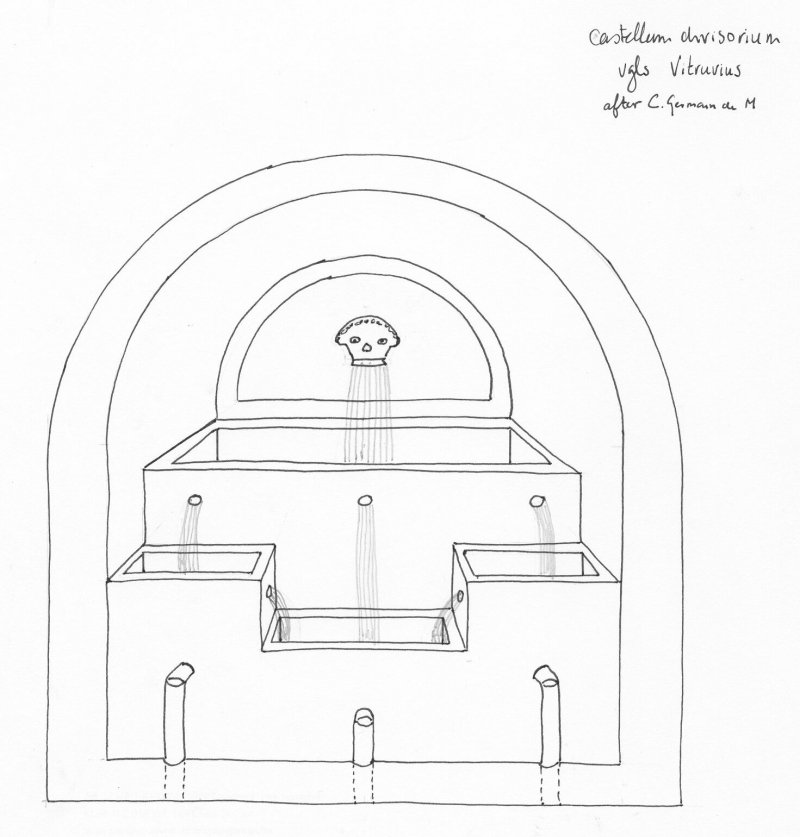
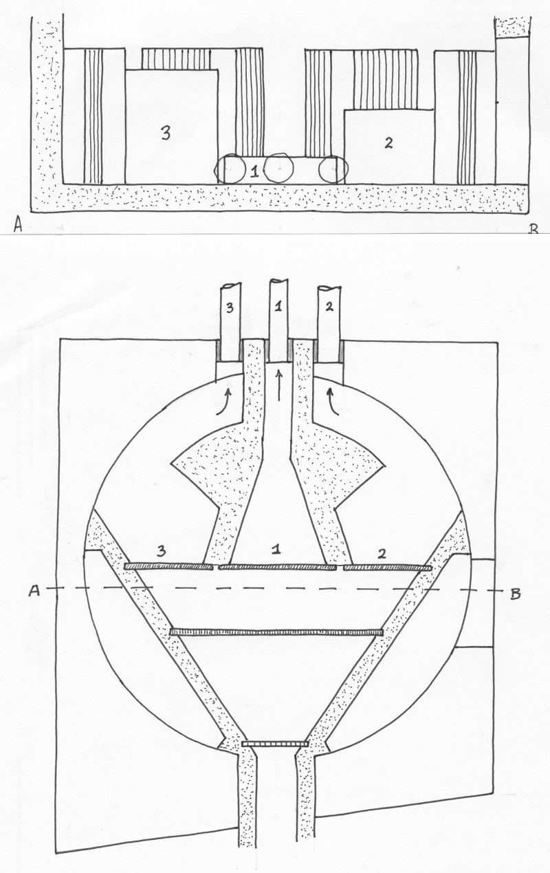
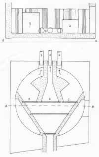
During the reign of Augustus Vitruvius, an army officer and architect, wrote a handbook De Architectura inwhich he described a prototype of a castellum (book 8, chapter 6 1b - 2):
1.b When it [the water] has reached the city, build a reservoir with a distribution tank in three compartments connected with the reservoir to receive the water, and let the reservoir have three pipes, one for each of the connecting tanks, so that when the water runs over from the tanks at the ends, it may run into the one between them. 2. From this central tank, pipes will be laid to all the basins and fountains; from the second tank, to baths, so that they may yield an annual income to the state; and from the third, to private houses, so that water for public use will not run short; for people will be unable to divert it if they have only their own supplies from headquarters. This is the reason why I have made these divisions, and also in order that individuals who take water into their houses may by their taxes help to maintain the conducting of the water by the contractors.
Unfortunately a castellum based on this principle has never been found by archaeologists.
Agrippa (....) was the first "manager" of the waterdistribution in Rome (in Latin: aquarius). One of his successors was Frontinus during the reign of Nerva and Trajanus (100 AD). He wrote a book on the nine aqueducts of Rome at that time "de aquaeductu urbis romae" in which he mentions 247 (first and second order) castella in Rome alone (chapter 78).
| Aqueduct |
nr of castella |
| Aqua Appia |
20 |
| Aqua Anio Vetus |
35 |
| Aqua Marcia |
51 |
| Aqua Tepula |
14 |
| Aqua Julia |
17 |
| Aqua Virgo |
18 |
Aqua Alsietina |
0 |
| Claudia / Anio Novus |
92 |
| TOTAL |
247 |
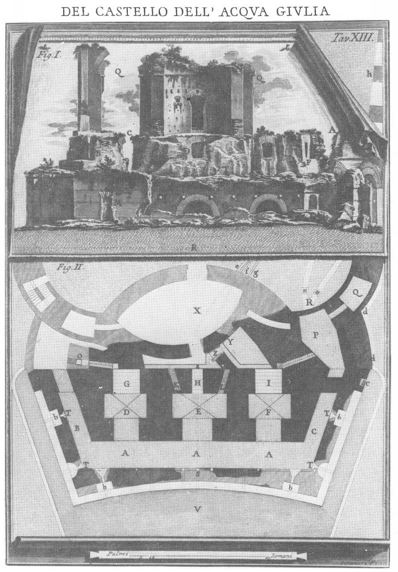
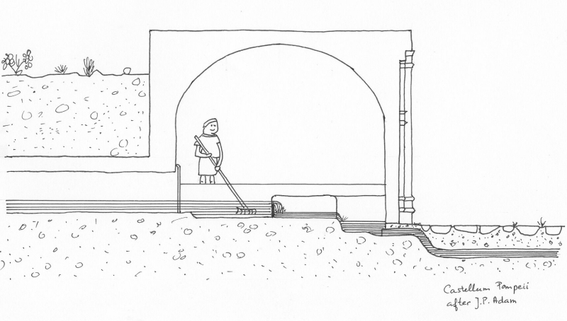
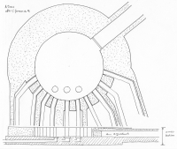
Two of the first order distribution basins have been found during excavations: in Nîmes and in Pompeii. Both are quite different in lay out and do not reflect the description of Vitruvius. A third could be found in Rome untill 1880, quite close to the Porta Maggiore. It was the terminus of both Claudia and Anio Novus aqueducts. At the end of the nineteenth century the basin was used as hay-barn and unfortunately caught fire. Piranesi made a fine drawing of the exterior of this castellum; In 1934 Van Deman described it as follows:
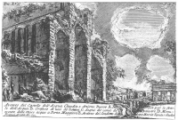 No remains are now traceable of the terminal reservoir, which lay about a hundred meters southeast of the Nymphaeum commonly known as the temple of Minerva Medica. An excellent engraving, however, was fortunately made of it by Piranesi before its almost entire destruction by fire. According to the plan of Lanciani, by whom some broken fragments were identified some decades ago, it measured on the outside 21,50 m. long and 14,20 m wide, and was divided into five chambers. The construction of the walls, so far as can be determined from the engraving of Piranesi, was of cut-stone with vaults of concrete (Van Deman1934).
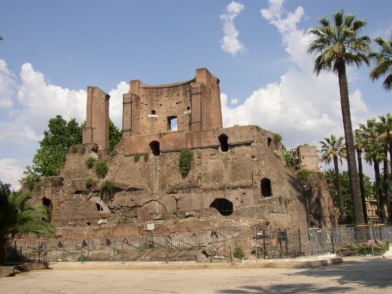
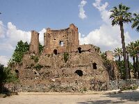
A second castellum is still present in Rome called "Trophies of Marius", the more official name is Nymphaeum Severi Alexanderi. It was a munera, an ornamental fountain in combination with a distribution basin. Archaeologists do not know for sure whether the water came from the Aqua Julia or the Aqua Anio Novus. Its impressive remains can still be seen at the Piazza Vittorio Emanuele.

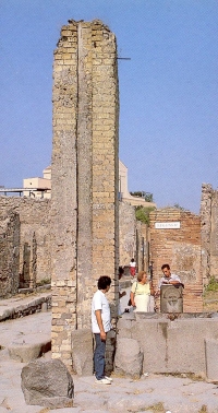
There are also some rare preserved examples of castella of the second order, most of them in Pompeii (see above).
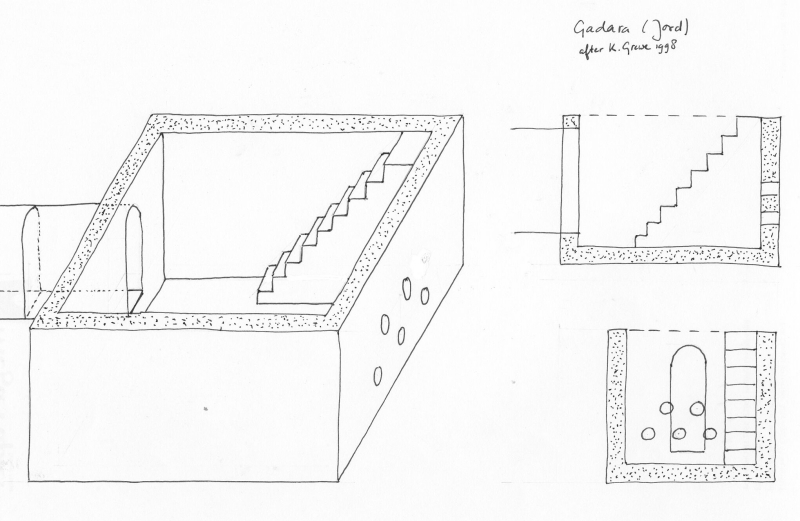
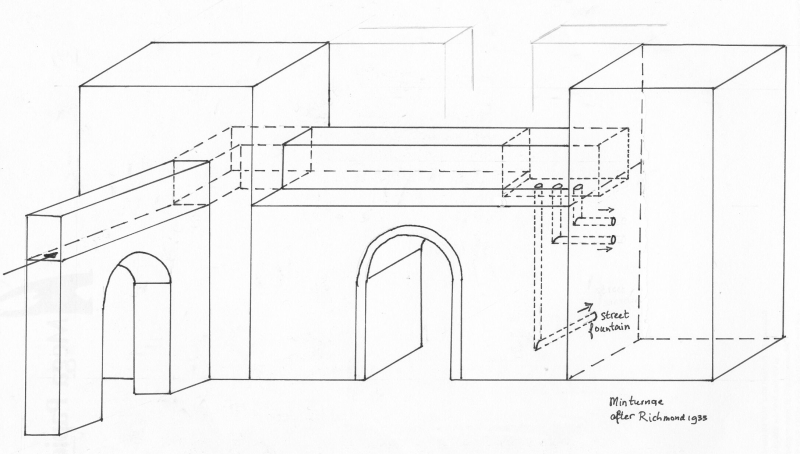
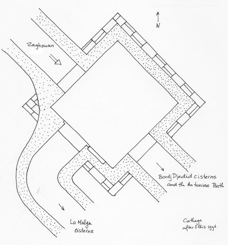
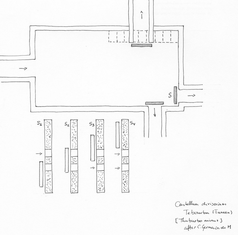
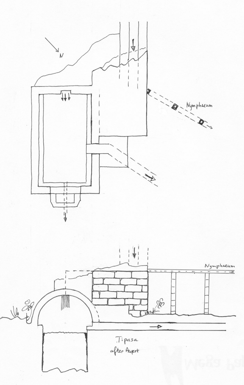
Especially in North Africa more castella divisoria can been found, all at the terminus of an aqueduct but not every basin transferred its water into pipes of lead or terracotta as for example if the destination was a cistern or a bath house (thermae). Unfortunately details of the original construction are often lacking when they are brought to light. An overview of some other castella divisoria:
 |
 |
 |
 |
| Umm Qais - GADARA (Jordan) |
Minturno - MINTURNAE (Italy) |
Carthage - CARTHAGE (Tunisia) |
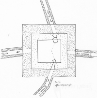
Tebourba - THUBURBI MINUS
(Tunisia) |
 |
 |
 |
 |
| Pompeii - POMPEII (Italy) |
Nîmes - NEMAUSUS (France) |
Pompeii - POMPEII (Italy) |
Tipasa - TIPASA (Algeria) |
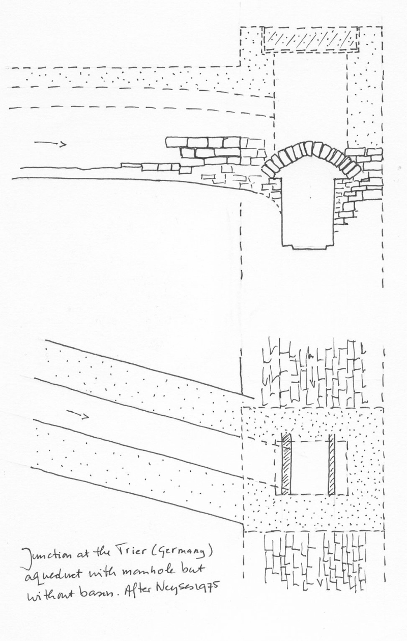
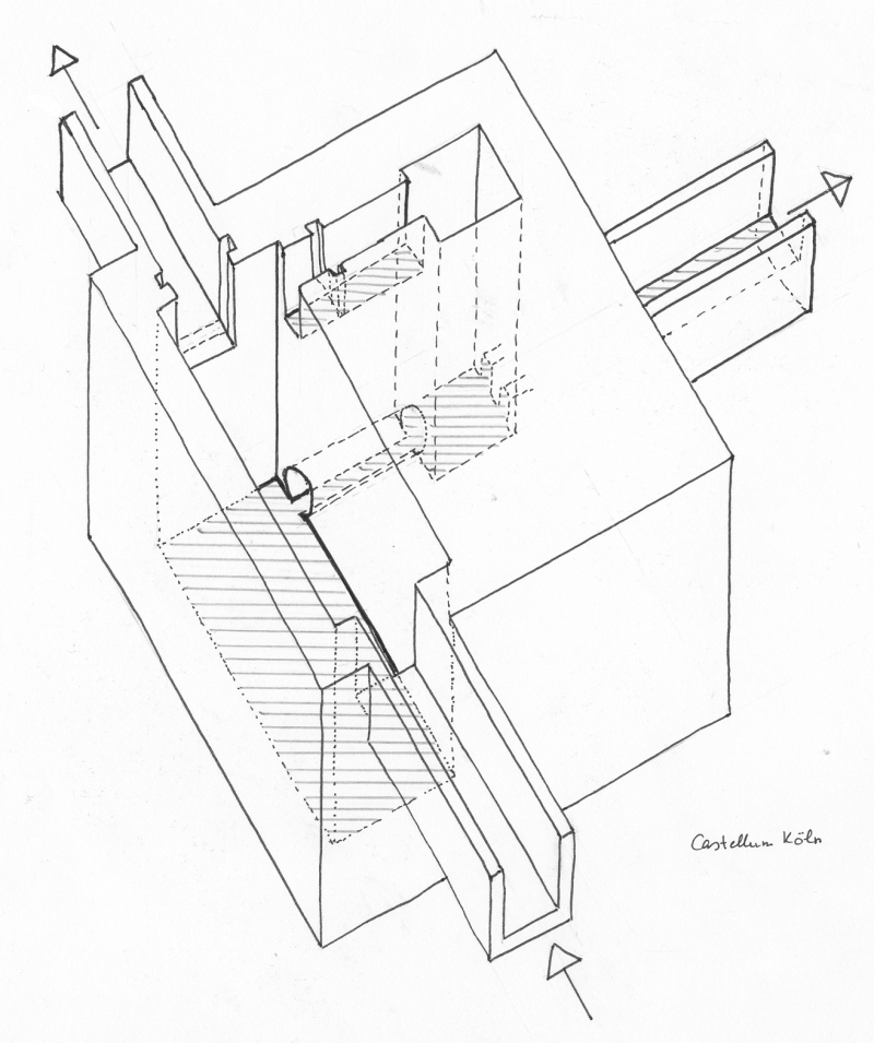
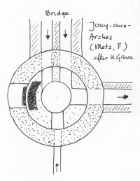
3. Junction or Splitting basin
Most aqueduct systems consisted of several tributaries joining to a main line, or main lines branched to serve servearl locations.
Where tributaries met one could opt for a real joint or
or a basin. Joints were seldom found in pipeline aqueducts outside the city but
there are a few examples of joints in masonry channels: at Rome (Osteriola), Lyon (Saint Romain au Mont d'Or, France),
Rome (Grotte Sconce, where one aqueduct discharged into (an) other(s)) and Cologne (Kallmuth, Germany), all without separate basins.
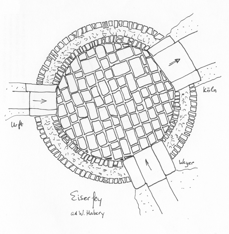
On the other hand there are serveral examples of junction basins e.g. near Eiserfey (Cologne aqueduct, Germany) and Wissous (Paris, France).
The Eiserfey basin may also have been used as an inspection point, public display and / or water drawing place because the basin had low walls
and was open to the air. Because of lack of archaeological finds it is in many cases unclear how conduits were split or united
(Hurth - Hermullheim in the Cologne aqueduct (Germany)); the branch off of the Sette Bassi line from the Anio Novus aqueduct near Rome).
 |
 |
 |
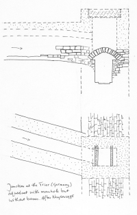
| Aqueduct of Köln (Germany) |
Aqueduct of Trier, junction without basin |
Aqueduct of Metz - France |
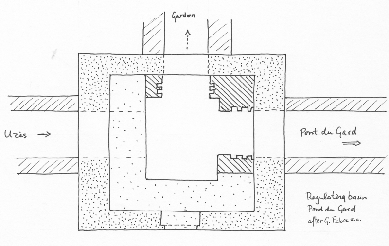
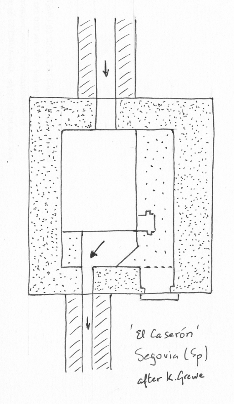
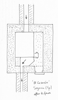
4. Regulation basin
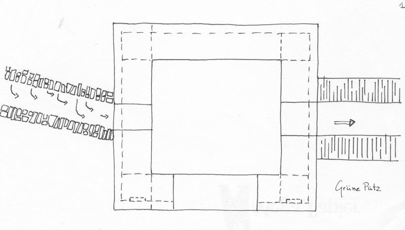
Under certain circumstances it was necessary to divert water away from the aqueduct: in some cases the source was too abundant in a specific season and could ruin the conduit, or the aqueduct needed draining for inspection or maintenance. In all cases there was a need to divert the water, mostly into a river nearby. The best known such drains are in the aqueduct of Nîmes (Uzčs and just before the Pont du Gard, France), Cologne (Grüngürtel station, Germany) and Segovia, Spain (just before the famous aqueduct bridge in the city).
 |
 |
 |
| Aqueduct of Nîmes (France) |
Aqueduct of Segovia (Spain) |
Aqueduct of Köln (Germany) |
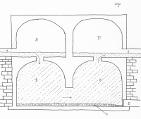
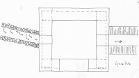
5. Settling basin
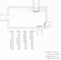
Settling basins were built to get rid of all kinds of pollution and were mostly situated near the source of an aqueduct and / or near the end, just before the terminal castellum divisorium, the water distribution centre of a town or villa. Some basins had a special outlet to discharge the dirt, in other cases the debris had to be removed periodically by hand. The best known examples were at the aqueduct of Cologne (Grune Putz, Germany) and Rome (Aqua Virgo tanks)
Along the Gier aqueduct of Lyon (F), one manhole was present every 77 meter (2 actus). Every second manhole was a little deeper than the floor level of the aqueduct and in this way served as a settling facility.
 |
 |
 |
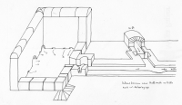
| Fabretti's drawing of a settling basin in the Virgo aqueduct in Rome |
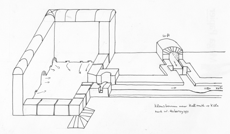
The source of the aqueduct of Köln (Germany) was a infiltration facility (left) directly followed by a settling basin |
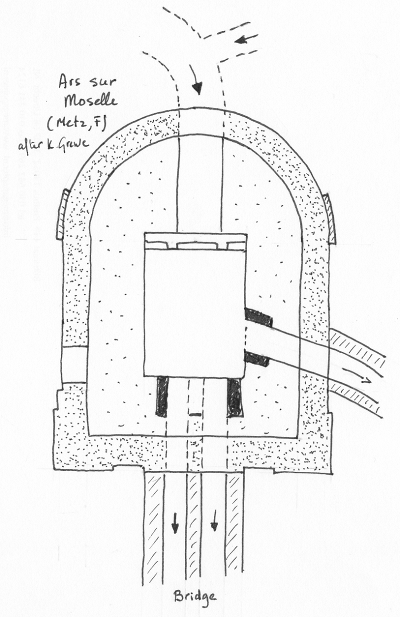
A more complex basin including a settling facility in the aqueduct of Metz (France) in Ars-sur-Moselle |
6. Collecting basin
There were different ways Roman aqueducts tapped their water sources: river intakes, dams, infiltration galleries, well intakes and spring boxes (see Source). In the last two cases the water was collected in a impermeable basin, the start of the aqueduct conduit, in most cases followed by a settling tank to get rid of debris. Well intakes usely tapped the groundwater while spring boxes were made to curb the active spring. The best researched collecting basins are the ones of the aqueducts of Nîmes (Fountaine d'Eure, France) and Cologne (Klausbrunnen, Germany) and Sens (Noé, France).
 |
 |
 |
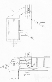
| Aqueduct of Köln (Germany) |
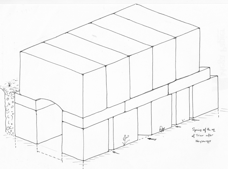
Aqueduct of Trier (Germany) |
Aqueduct of Paris (France) |
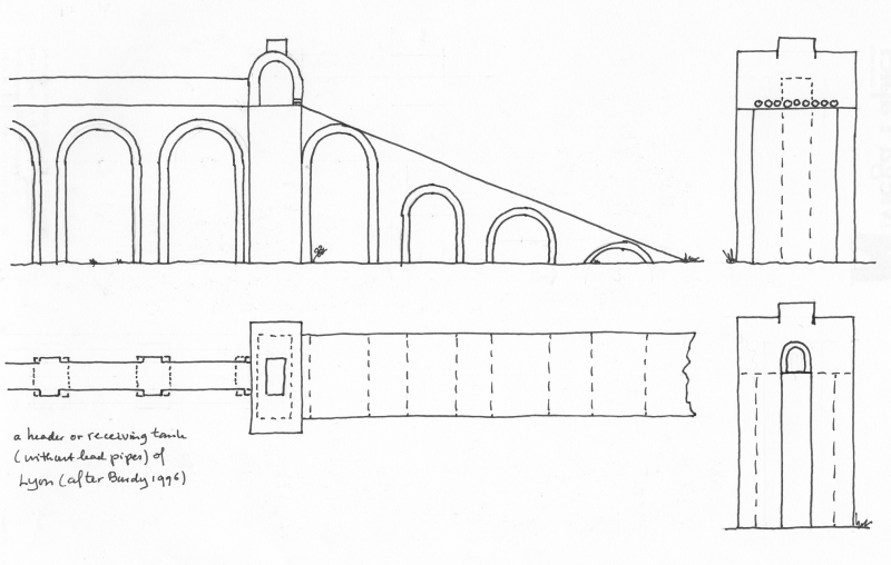
7. Transition basin
Most transition basins can be found in header and receiving tanks of a siphon.
 |
| Transitionbasin / headertank in one of the nine siphons of the the aqueduct of Lyon (France) |
8. Waterfall (with stilling basin)
It is a common misconception that a steep aqueduct channel is advantageous because it can transport a lot of water quickly. Fast moving water
has such a destructive power that it can damage the aqueduct channel and related structures. For this reason, most Roman and modern aqueducts
have a relative shallow gradient, so that the water does not move fast. In some cases however, when the source is high up in the hills,
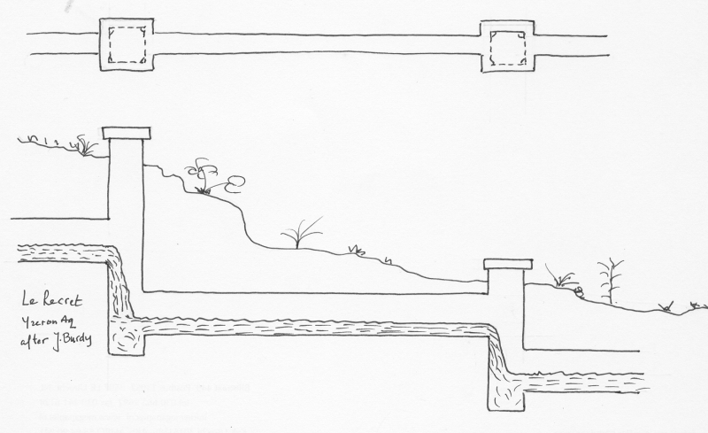
it is necessary to make the aqueduct steep. In such cases special constructions are needed to avoid damage. Especially where the slope is steep,
stilling basins were used to lose height, sometimes in a cascade setting. The best known examples were the subterranean dropshafts of
Le Recret in the Yzeron aqueduct of Lyon (France) and the ones on the Montjeu aqueduct of Autun (France).
Sometimes stilling basins were also used after smooth chutes and stepped cascades, to dampen wave energy.
 |
 |
 |
| Brevenne-aqueduct (Lyon F) |
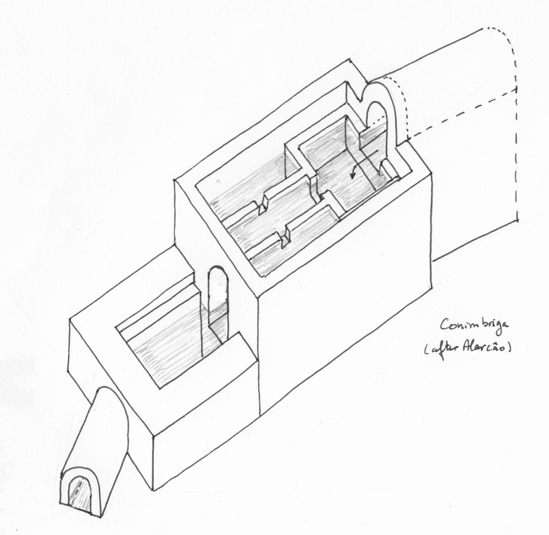
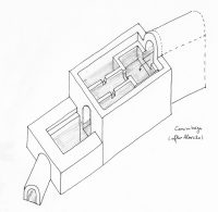
Aqueduct of Conimbriga (Port) |
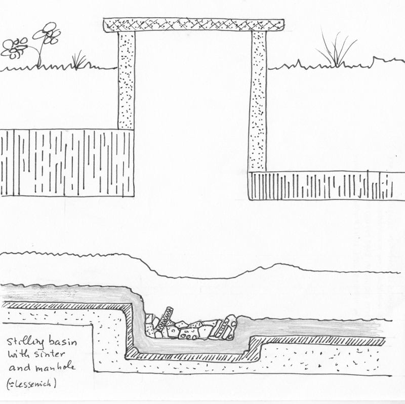
Typical example |
9. Street-side basin