Caesarea (Israel)

Roman aqueducts: Caesarea Maritima (Israel) Caesarea - CAESAREA MARITIMA
For the photo's, see below
For the complete website

The ruins of the ancient city Caesarea Maritima are located by the sea-shore of Israel, about half way between modern Haifa and Tel Aviv. Caesarea was founded in 10 BCE by King Herod of Judea (37-4 BCE) as an urban centre next to an artificial harbour. In 6 CE, Caesarea was declared the seat of the Roman governor and the political capital of Judea, subsequently named Syria Palaestina by the Emperor Hadrian after the suppression of the Bar Kochba revolt (132-135 AD), and became the largest city in the province. The city had abundant supplies of water delivered from wells, cisterns, and aqueducts.

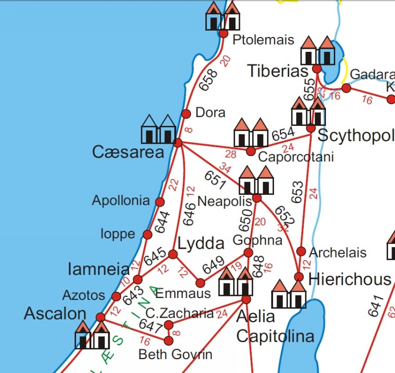
The Tabula Peutingeriana (Peutinger map) is an itinerarium depicting the road network in the Roman Empire. The original map of which this is a unique copy was last revised in the fourth or early fifth century. It measures about 0,35 m in height and 7 m in length.
Dr. W. Bruijnesteijn van Coppenraet made this outline (from: De Romeinse reisgidsen, 2006).
Distances in Roman miles (1482 m). Vignettes are Mansiones: official stopping place along a Roman road with (or without) some facilities).
Route On the map to Present name
658 Dora ancient Tantura / Nashlohim
  Ptolemais Akko / Acre
654 Legio / caporcotani /
Maximianopolis
Al Lajjun
(a corruption of Legio)
  Scythopolis / Nysa Beth She'an
651 Neapolis Sechem / Nablus (WBK)
646 Lydda / Diospolis /
Georgioupolis
Lud / Lod
644 Apollonia / Sozousa Apollonia-Arsuf

Three aqueducts

Two aqueducts arrived at Caesarea from the north, named the High level and the Low level aqueduct; a third one - a pipe line - came from the south. The High level aqueduct, apparently constructed in the 1st century CE, started at the Shuni spring located about 7 km north-east of the city (see the aqueduct map nr. 3). Its head of water when reaching Caesarea was 8.5 m asl, with long sections supported by arcades. The average effective delivery of the High level aqueduct was calculated as 300 m3 per hour and considered an abundant amount for a city of 50,000 inhabitants. Such a delivery, about 145 liters per day per capita, is similar to the consumption in modern cities of developed countries. It underwent several alterations and repairs.

Overview of both Roman aqueducts of Caesarea Maritima: the High level aqueduct (from 1 - 6 - 8 -12) and the Low level aqueduct (7 - 12).
From: Tsuk 2011
Map of the Nahal Taninim dam (8) and its regulation facility (3). Numbers 4 and 5: the start of the Low level aqueduct. From: Tsuk 2011

The Low level aqueduct issued from a reservoir created by two dams across the Tanninim valley, about 4 km north of Caesarea. Its channel was quarried into bedrock, wherever possible, or constructed on sand in the southern segment. The head of water in the Low level aqueduct is calculated as 6.3 m asl according to sinter sediments on its plastered walls. The reservoir was spread over 600 hectares, and served as a huge elevation pond to allow the flow towards Caesarea by gravitation. The water supply was governed by a triple sluice gate - one of the best preserved of antiquity. The average effective delivery of the Low level aqueduct was calculated as 800 m3 per hour, some 3 times the delivery of the High level aqueduct. Its construction date is estimated at the end of the 4th or early 5th c CE (Porath 2002) and was still in use by the 6th c.

A third aqueduct system comprised of a ceramic pipe line from a spring called 'En el Assal in the lower basin of Nahal Hadera, some 4 km S-SE of Caesarea (not on the maps). The construction dated is probably in the 4th c CE. Today its delivery 1 - 2 m3 per hour, but this was reduced in the 20th c due to overpumping of modern wells. The pipeline was made of clay pipes, each 0,44 m long, 0,18 - 0,22 m in diameter and 0,01 m thick, at the outside coated with a concrete layer of 0,20 m.

The High level aqueduct

The high-level aqueduct had exploited all of the topographical suitable springs in the vicinity of the city. When the population grew and the demand for water exceeds the supply, additional sources were required. The main source was 'En Shuni (nr 3 on the aqueduct map), 6 km NE of Caesarea and 11,80 m asl. All other smaller sources were annexed as auxiliary sources: 'En Tsur, 'En Ami (nr. 2), 'En Tsabarim (nr. 1) etc. The initial course of the aqueduct from 'En Shuni lay below the surface to permit a better flow of the diverted water.
A segment of an underground course, dated to a later phase of the aqueduct, was found 540 m SW of 'En Shuni. The aqueduct is seen again in the valley of Nahal Taninim (the Crocodile river), about 500 m SW of the underground segment.

The tunnel in Mey Kedem
For about 7 km the 'En Tsabarim spring was connected to the trunk line of the High level aqueduct by a tunnel of 250 m which can be visited at Mey Kedem (nr. 2), from the second to the seventh shaft. After a short introduction one can walk in the unlighted channel less than 1 m wide and 1,5 m high. Near the end the water is 0,5 m deep, cool and refreshing. Mei Kedem is about 1 km W of Amikan, along route 6533.

For more info (both in Hebrew and English): Mey Kedem
At some places a tunnel was built, at other places - in order to reach an elevation up to 1,5 m above the ground - solid stone walls (often named substruction) were used; to achieve higher elevations, long arcades were built.
After tunneling through the central kurkar (local fossilized sandstone) ridge of the Carmel Mountains (nr. 8, tunnel of Jazzer a-Zarka), the aqueduct turned SW for 700 m and then south to Caesarea, running parallel with the coast line. The aqueduct emerged from the tunnel in an area of sand dunes on the coastal plains which acted as a protected blanket. During the sixties circa 500 m arcade was cleared and is still visible.
The aqueduct is seen once more, inside the Byzantine fortifications of the city, and it terminated in front of the inner city wall in a small basin, the head of the distribution system (see below).

Wherever the aqueduct is damaged, especially along the beach, it can be seen that the aqueduct was composed of two channels, A and B, and built in different phases, with a pronounced seam between them. Channel B was places on the right (outer) side - in the direction of the flow - of A. Channel A was built before B as is clear from different facts, like that A has a cornice on both sides while B has one only on the outside.

In the eastern section - between the Nahal Taninim river and the splitting N of Beit Mananya (nr. 6 on the aqueduct map), three clay pipes - each 0,17 m in diameter - were inserted inside channel B, on top of its floor (see cross-section I). In the western section, W of the Jasser a-Zarka tunnel, channel B was filled in and a narrow channel (C) was built above (see cross-section II).

The by-pass and the tunnel

The high level aqueduct had probably been in use for about three centuries when a section about 530 m long at the Nahal 'Ada valley was put out of use. A deviation to the south was built N of Beit Hananya apparently to avoid an area sinking into the swamp, made worse by the reservoir of the Low level aqueduct (see below).

The Jasser a-Zarka tunnel is 442 m long and equipped with 15 shafts / manholes (in Latin: putei), each 6,6 - 13,4 m deep and they range from 11,5 - 37,4 m apart. These intervals are usually about twice their intended depth.

The construction

The channels were built of rubble cemented with lime mortar. The use of cheap materials rather than ashlar blocks, was common in Roman aqueducts. The channels were plastered with lime plaster on their inner and exterior faces down to the supporting structure. The free-standing parts of the supporting structure below (whether solid walls or arcades) were built of local kurkar ashlars, infilled with rubble and mortar. The buried sections are wider than the upper structure. The upper course of the supporting walls was decorated with a cornice projecting 16-21 cm.

The high level aqueduct saw several repairs. Many arches, particular those below channel B, detoriated and were replaced or buttressed.
All the channels of the high level aqueduct were roofed, to protect the water from dirt, theft, sand, and light. In the subterranean sections manholes for inspecting the water flow and to release air pressure, were built at irregular distances.

The distribution

We still know little of the system by which water must have been distributed inside the city. Limited sections of clay and lead pipes had been uncovered but no overall picture has been presented.
Urban Roman aqueducts usually terminated at a distribution basin (castellum divisorium), located at a high spot at the edge of a city. At Caesarea the difficulty facing the Roman engineers was that all of the sources, and likewise the termini, were at relatively low alti-tudes. We have no information on the distribution systems of the Low level aqueduct and the Southern pipeline. Until recently it was assumed that the high level aqueduct crossed the so-called inner city wall for an unknown destination, but in 1990 it was observed that it terminated by a distribution device just in front of this wall.

The device is crowned by a basin whose external width at that point conforms with the combined external dimensions of channels A and B including their dividing walls (see drawing below). The length of the basin is uncertain since the connection between it and the channels was destroyed, only the stumps of the last two arches being preserved. The basin or distribution device had a flat floor about 0,35 m lower than the channels A and B nearby, three vertical walls, and one side open to the twin channels on the north . The basin's walls did not survive to their original height, which was about 1,9 m (as there is no benefit in surpassing the walls of the adjacent aqueduct). The external vertical walls have encrustations left by water seeping and overflowing. On each of the E and W vertical walls a vertical groove is present to hold a clay pipe 0,09 m in diameter.

This device evidently served as the terminus for the high level aqueduct and the head of the distribution system, in effect a kind of castellum divisorium.
The water was then distributed from this castellum across the city in pressure pipes, mostly made of pottery, sometimes of lead.

Inscriptions along the High level aqueduct
Some ten inscriptions have been found, attached to the High level aqueduct of Caesarea. Nine are in Latin and one is in Greek, the latter referring to repairs made by order of the Roman proconsul of Palestine in / after 385 CE. Some were found in two heaps of stones and rubble at both sides of a 'modern' (first quarter of the 20th c CE) drainage channel and the aqueduct where the detour - west of Beth Hananya - joints with the original channel.
Those nine Latin inscriptions make mention of three Roman legions active in repairing (not the actual construction) the High level aqueduct during Hadrian's reign, about 130 CE: five inscriptions refer to Legio X Fretensis (of the sea strait), two to Legio VI Ferrata (ironclad), one to Legio II Traiana Fortis (valiant), and another one is uncertain.
The one attached to the aqueduct close to Beth Hananya - just before the start of the detour, see map - comprises of legionary insignia of the Xth Roman legion and a tabula ansata (table with dovetail handles) with the text:

IMP CAES / TRAIANVS / HADRIANVS / AVG FECIT / PER VEXILLATIONE / LEG X FRETE

which reads as:
Imperator Caesar Traianus Hadrianus Augustus [caesar Hadrian 117 - 138 CE] made [this] by means of a detachment of the legio X Fretensis (see Olami 1975).

The Low level aqueduct

Purpose
There is still discussion about the purpose of the Low level aqueduct. The options:
  1. Home consumption: the water retained in the reservoir was not suitable for drinking water (too much chloride and partly shallow still water); remains of any purification installation have not been found
  2. Irrigation: there are no openings in the walls to divert the water; water was partly contaminated (see above)
  3. Public consumption via nymphea or street-fountains, or sanitation in the bath houses and/or public toilets: the potential supply capacity of the Low level aqueduct was much higher than needed here
  4. Other purposes: no contemporary water power engines like mills have been found with in the area where the Low level aqueduct was proven or supposed. The idea of Y. Dray that the Low level aqueduct water was used to flush and from the harbour is still under discussion.
Primarily based on Porath 2006

This was the largest aqueduct in the country in antiquity. It was built of roughly cut stones cemented with grey lime mortar and plastered with a layer of reddish lime plaster. The channel rests on a wide foundation and is carried by a solid supporting wall. The channel is 1,8 m wide and 1,4 m high excluding the vaulted roof. Its walls are 1,1 m thick and the barrel vault was 0,35 m thick. On the roof there are several openings at irregular intervals, like those on the high level aqueduct. Despite its insignificant gradient its maximum theoretical supply has been estimated at 2500 m3 per hour. Yet the real delivery of this aqueduct was much lower, for water never filled the total volume of the channel. The travertine encrustation on the walls, which reflects the maximum flow, rose to about 0,85 m above the floor (60% of the total height).

The source of this aqueduct was several springs ('Einot Hananya, 'Bin Thimsakh, etc.) emerging in the swampy Nahal Taninim valley some 5-6 km north of the city. The ancient architects wishing to use these springs by gravitation faced a major difficulty: the springs gush at 3,5 to 4 m asl, whereas most of the urban area of Caesarea lies at 5 m asl or higher. Their solution was to raise the water level to the required height by constructing a 197 m long (West) dam at the point where Nahal Taninim cuts through the kurkar ashlar ridge. The reservoir formed behind the dam was bordered on the north by another (North) dam 900 m long. The accumulated water consisted of the annual discharge of the springs and the periodic winter flow of Nahal Taninim and its tributaries.

The water stored behind the dam was diverted into the Low level aqueduct, and the aqueduct ran directly south for a distance of almost 5 km. The first section runs along the W slope of the central kurkar ridge as a rock-hewn channel for about 1350 m; further south it departs from the ridge and continues as a massive stone construction. The Low level aqueduct passed under the high level aqueduct after the latter emerged from the tunnel of Jasser a-Zarka. It can be followed south to within 150 m to the north Byzantine wall of Caesarea, where it is lost under the sand.
We do not know how it entered the city or by what means the water was distributed. There is no outlet along the exposed sections and it would appear that all of its water went to the city, apart from later added branch lines.


Primarily based on Porath 2002

Wilke Schram

Time Table

63 BCE - 132 CE Early Roman
132 - 324 Late Roman
324 - 638 Byzantine
638 - 1099 Early Islamic
1099 - 1291 Crusader
1291 - 1516 Late Islamic
1516 - 1917 Ottoman
1917 - present Jewish settlement

Caesarea - CAESAREA MARITIMA

Item Info
Length km
Cross-section m x m
Volume m3/day
Fall %
Period Augustan
Features


Recommended literature :
  • Y. Porath: The water-supply to Caesarea, a re-assessment (in: D. Amit: The aqueducts of Israel 2002 pag. 104 - 129)
  • Y. Peleg: The dams of Caesarea's Low level aqueduct (in: D. Amit: The aqueducts of Israel 2002 pag. 141 - 147)
  • Y. Porath: What was the purpose of the Low level aqueduct to Caesarea Maritima? (in: G. Wiplinger: Cura Aquarum in Ephesus 2006, pag 255 - 257)
  • T. Tsuk: Water at the end of the Tunnel, touring Israel's ancient water systems (in Hebrew), 2011
  • Rendering water unto Caesarea (M. Gilad, in: Haaretz August 19, 2011)
  • Aqueducts and tunnels (E. Bensinger, in: Sightseeing in Israel Jan 30,2008)
Recommended websites   :
How to visit                  : see above
HOME More literature on more aqueducts Last modified: October, 2013 - (webmaster)


Entrance

Inside the tunnel

Layers

Depth

Niche

Shafts

Beit Hananya

Cross-section

Bypass

Inscriptions

Milestone

Incrustation

Unfinished aqueduct

Nahal Taninim dam

Regulation facility

Details of the sluices

Wooden boards

Windlass

Regulating the water flow

Behind the sluices

Byzantine water mill

Byzantine flour mill

Chutes

Ottoman mill

New sluice

Three channels

Channel A and B

Keystone and cornice

State of preservation

Side branch

Ceramic pipes

Well known photo

Castellum

Low level aqueduct

Watertight plaster

Model of Caesarea

Roman theater

Sluice gate?

Water for naumachia