| Description |
Line drawing |
Photo |
Extra |
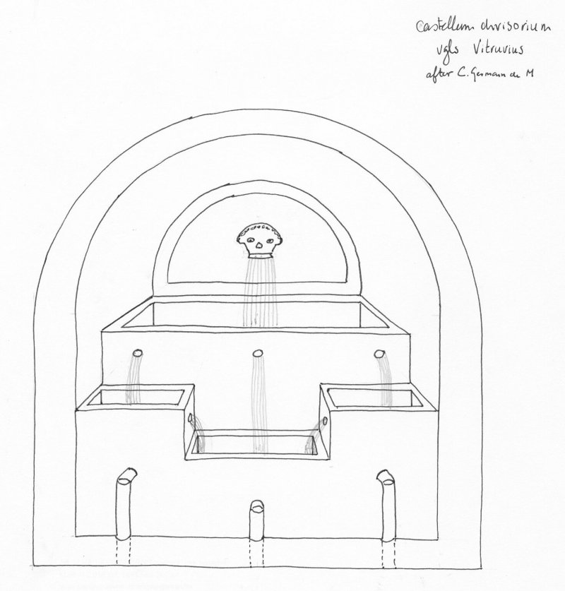
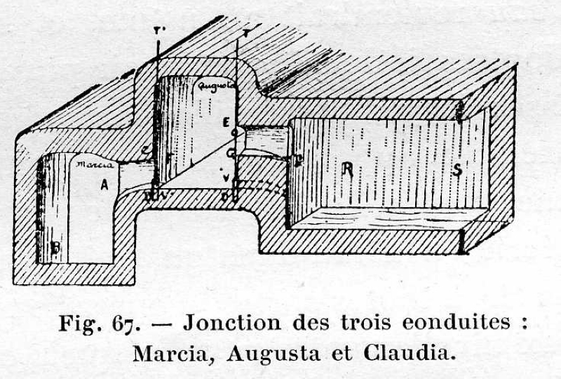
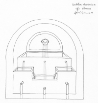
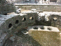
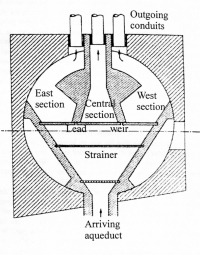
Vitruvius' distribution basin.
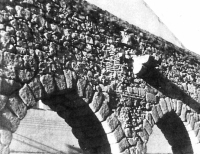
The well known distrubution basin of Vitruvius (8.6.1-2) as depicted
by Germain de Montauzan (1908). |
 |
|
|
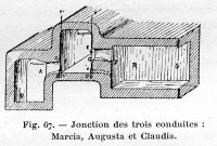
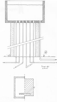
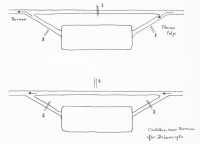
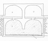
| Hypothetical distribution basin.The hardware translation of Frontinus (14.3) by Rondelet for the distribution of excess water of the Augusta source to the Aqua Marcia and the Aqua Claudia. See the work of Germain de Montauzan (1908). |
 |
|
|
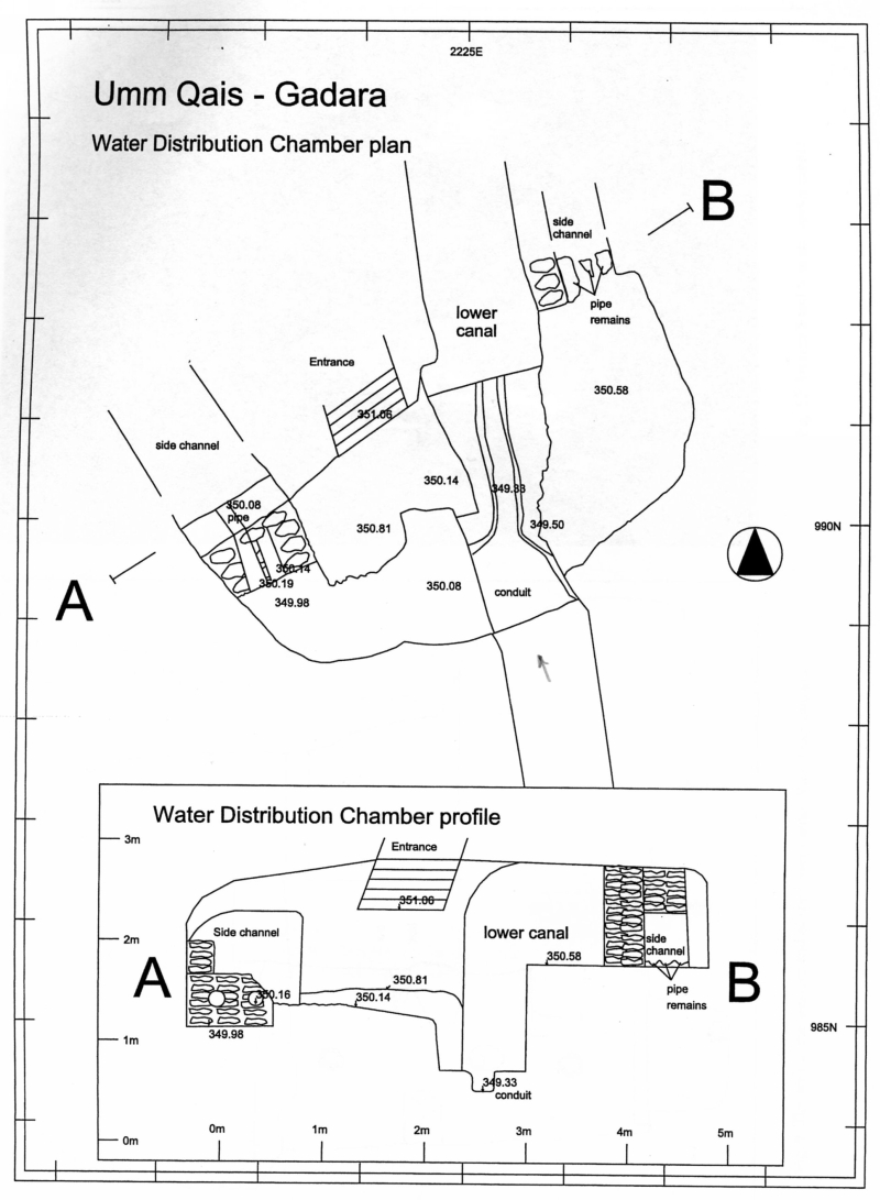
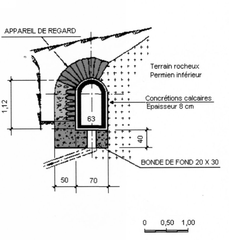
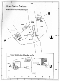
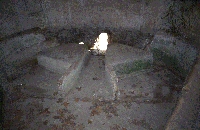
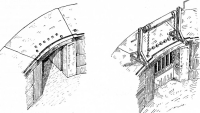
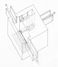
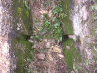
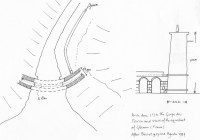
Umm Qais - GADARA (Jordan).
Subterranean distribution mechanism in the aqueduct of Gadara based on height differences. At left a branch equipped with pipes 0,83 m above the supply channel. At right a branch channel - possibly equipped with pipes - 1,25 m above the bottom of the main conduit. |
 |
|
|
Nîmes - NEMAUSUS (France).
The water of the Nîmes aqueduct was (also) distributed by means
of 5 pairs of holes in the side wall, whenever necessary to be blocked by (perforated) plugs. |
 |
 |
|
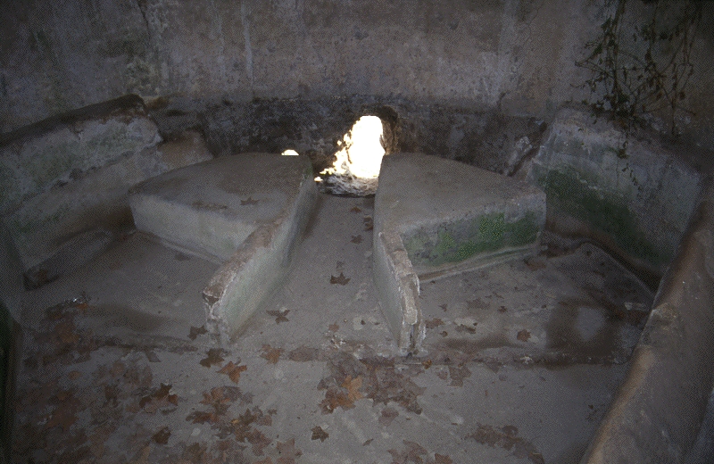
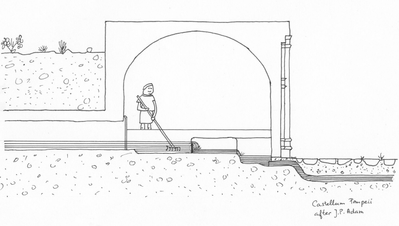
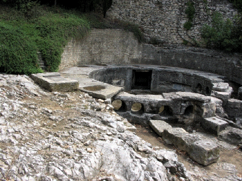
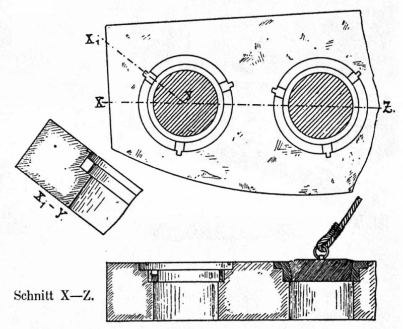
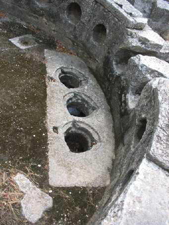
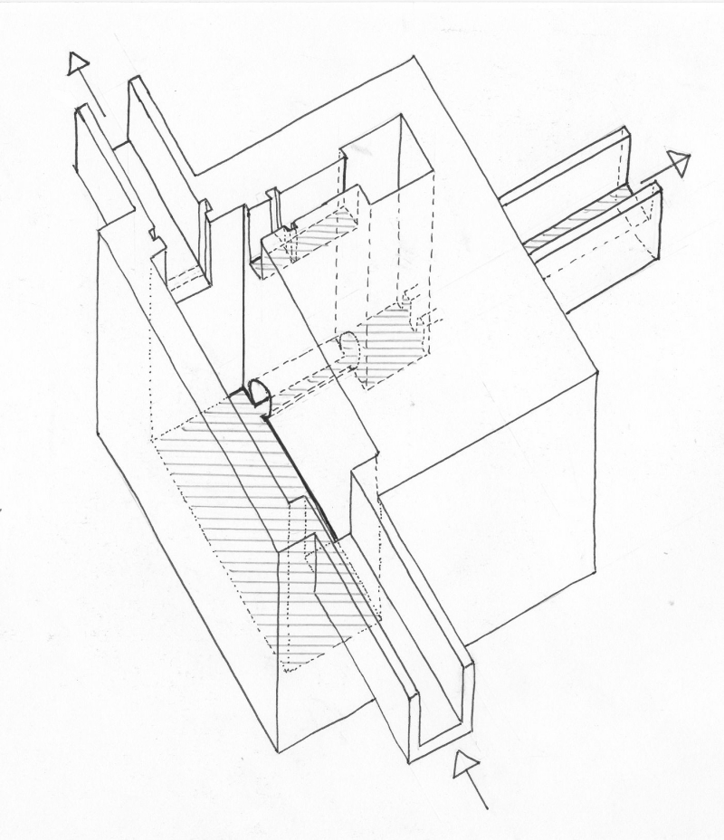
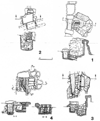
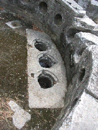
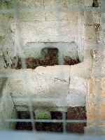
Pompeii - POMPEII (Italy).
Circular shaped distribution basin in Pomepii with additional constructions in the floor. Wedges in the horizontal openings (Ohlig) or plugs in the holes (Kessener) of the flow control slabs |
 |
 |
 |
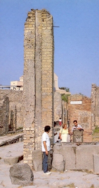
Pompeii - POMPEII (Italy).
Secondary distribution tower in Pompeii (Italy) necessary to reduce the water pressure because of the slope in the water distribution system. On the photo the lead water tank on the top is missing. |
 |
 |
|
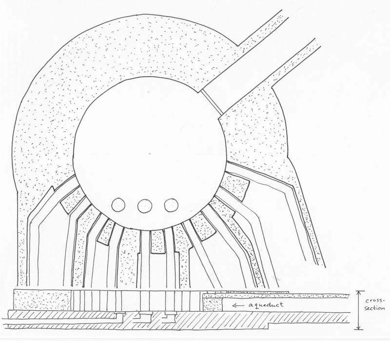
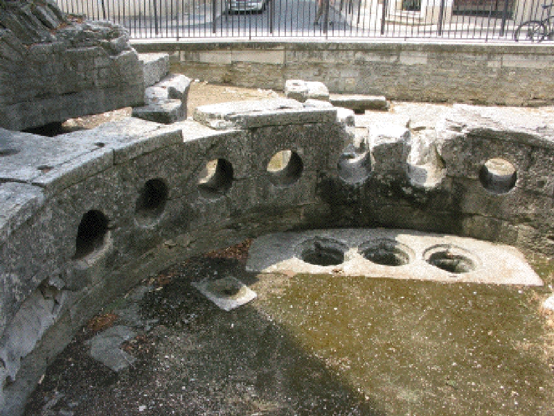
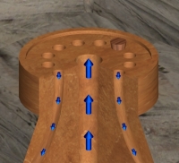
Apamea (Syria).
A distribution system based on a round table of stone with a stand-up collar with at the edge space for a ring of 12 vertical outgoing pipes, in the middle a somewhat bigger vertical inlet pipe. drawing ©C. Romeijn |
|
|
 |
Banias (Syria).
The distribution to the town of Banias was through a series of some 20 distribution basins places along the aqueduct channel. The outlet of each basin was a ceramic pipeline leading water to the city. |
 |
|
|
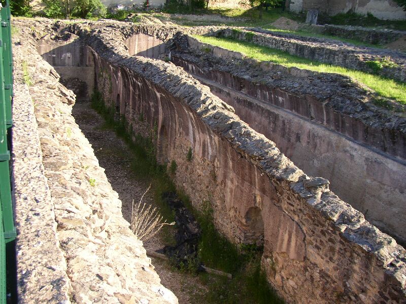
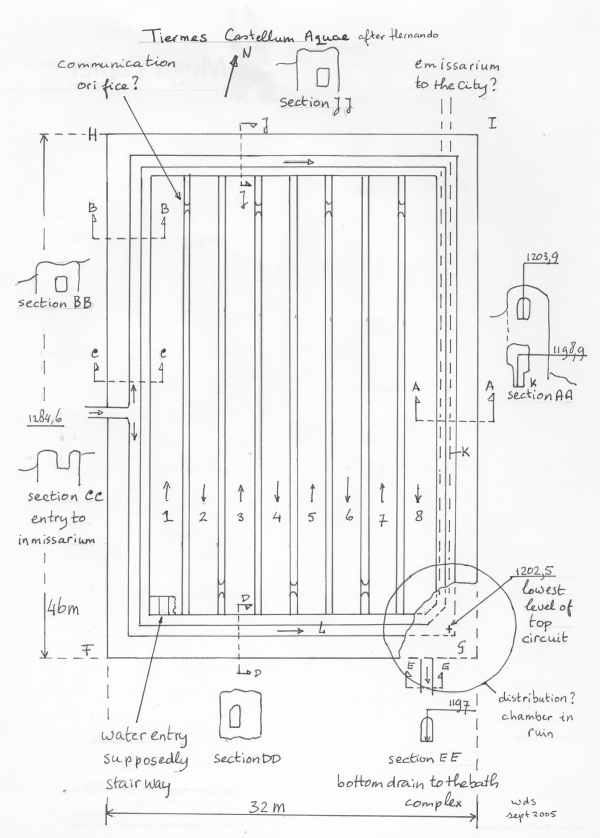
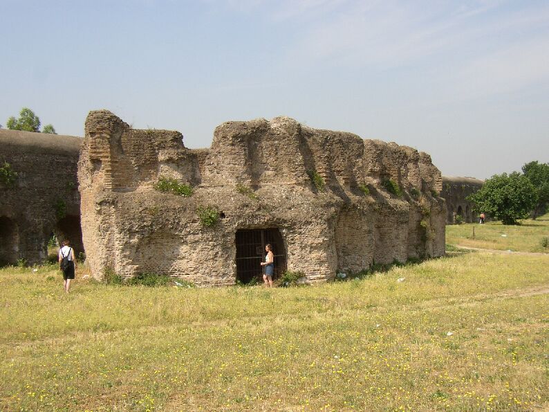
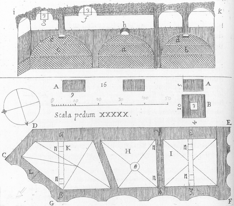
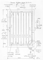
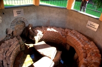
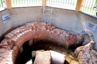
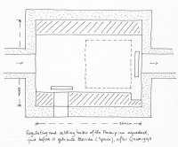
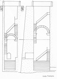
Tiermes (Spain).
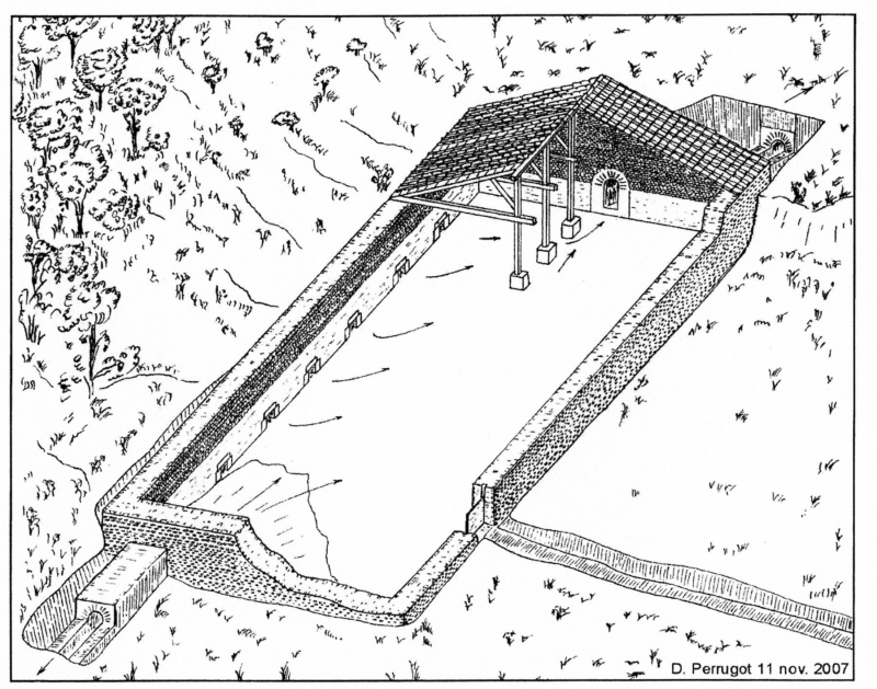
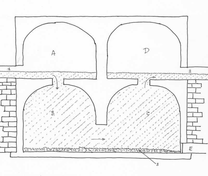
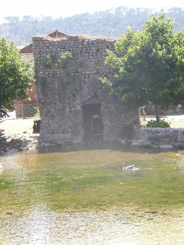
Water rooms and regulating mechanism
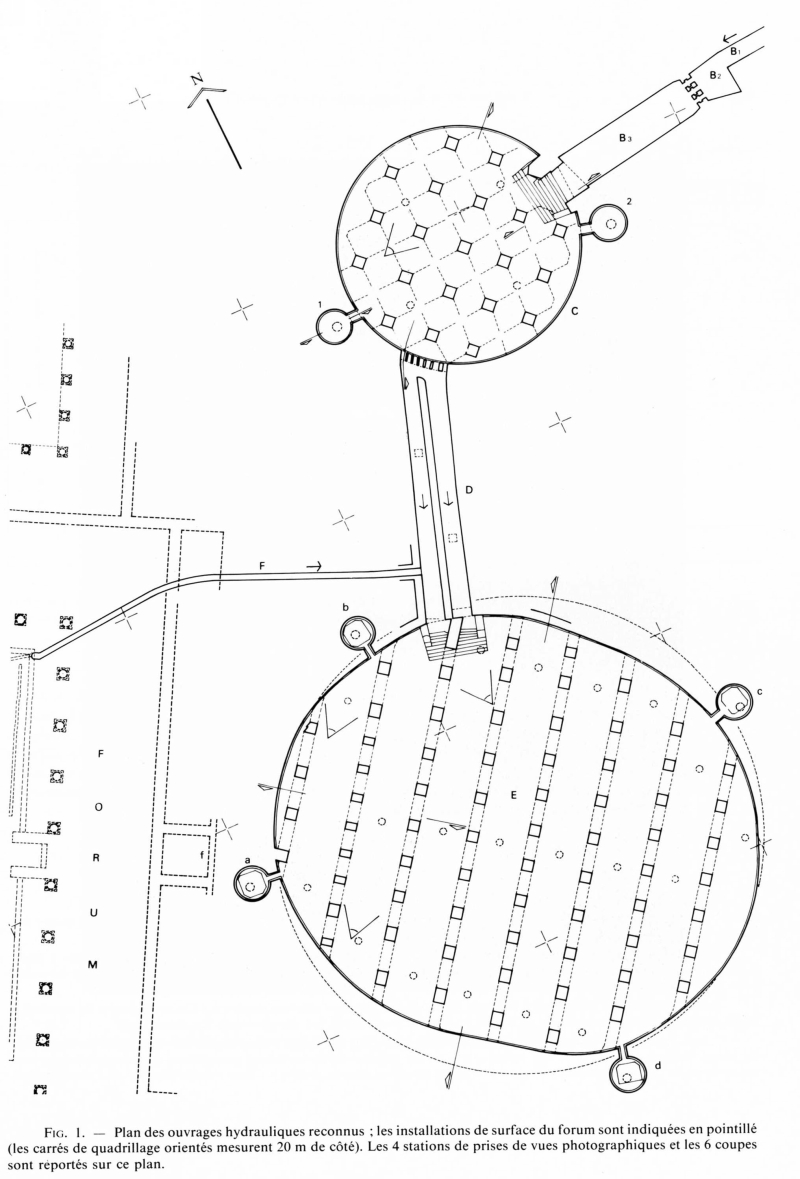
The aim of this reservoir, measuring 32 x 46m, 6m high with 3,5m thick walls, would have been the supply of water to the NE sector of the city
and the baths complex as a complement to the flow supplied by the southern artery. It was made up of eight linked water rooms with orientation
N-S (see drawing).
The water, under normal conditions, would enter through the "inmisarium" C and continues to corner F, entering water room 1 probably via steps.
The excess water would continue down channel L to the distribution chamber (?) situated in G. Through room 1 the water would circulate towards the
North end where there would be a communication orifice towards water room 2, flowing in the opposite direction towards the South, and successively
until reaching room 8 and the distribution chamber G. This circuit was used to prolong the circulation distance as much as possible and decant the
water well.
Judging by the direction of the gradient of the C-H-I-G canalization (about 4%) this section would have been used to give continuity to the water flow
(as a by-pass) to the chamber G whilst the water rooms 1 - 8 were cleaned or in repair.
The distribution chamber would be located at corner G, but is presently almost destroyed. It must have had a department inside where there would
have been a complex of channels and sluices used to send the water at will to the following locations:
- To the bottom drain E in order to empty the eight water rooms simultaneously or for sending water to the baths complex.
- To the emisarium at corner I through channel K to supply water to the NE sector of the city.
The plan of these eight water rooms had been a deduction based on scarce excavations so far of the surface area in the interior of the enclosure
of the "castellum aquae". This hypothesis will have to be confirmed as the excavation work progresses.
Based on the article "The Roman water supply to Tiermes" (Hernando2001) and private communication with the author Manuel Hernando
|
 |
|
|
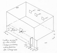
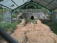
Mettet (Belgium).
Distribution basin near the Roman villa in Mettet with settling facility (in the front) supplying four area's of the villa (after De Maeyer1937). |
 |
|
|
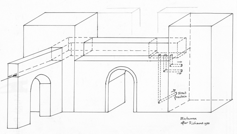
Minturnae (Italy).
The aqueduct of Minturnae entered the town on top of the city wall where the first
water distribution took place towards a street-side fountain and two unknown users (after Richmond 1933) . |
 |
|
|
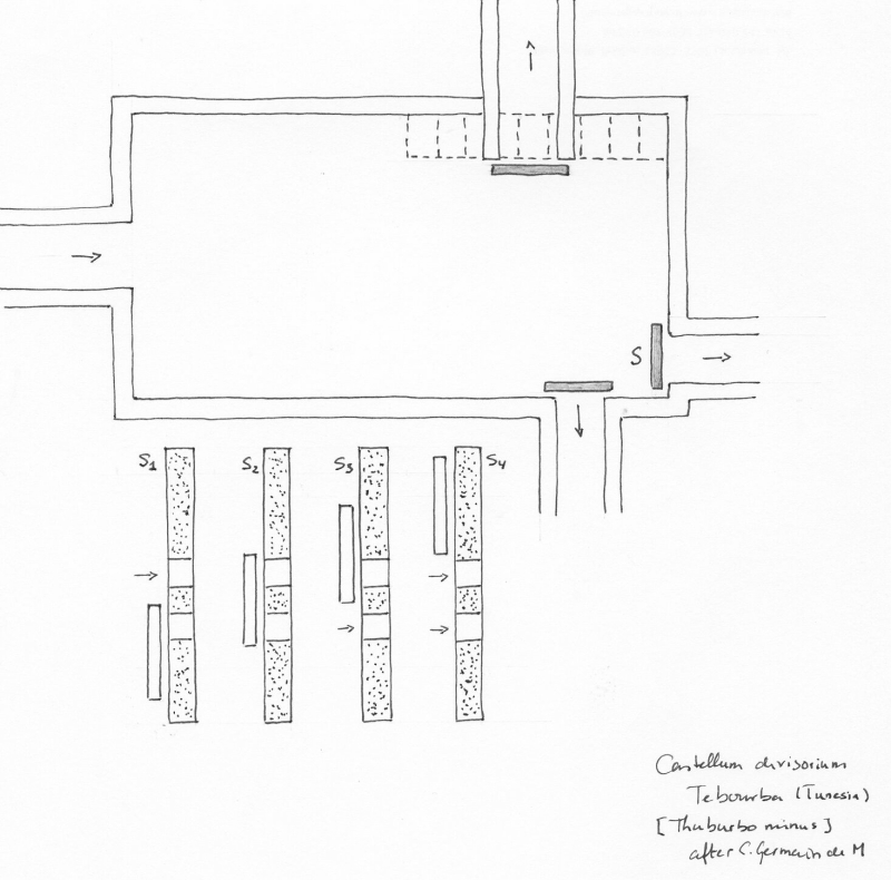
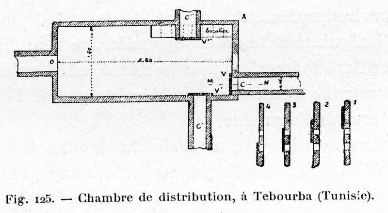
Tebourba (Tunisia).
Basin of Tebourba with one inlet and three outlets equipped with control mechanisms, two with the well known sluices, a third with a more complex system: two holes above each other at will open or closed depending op the level of the slide (after Germain de Montauzan 1907) |
 |
|
 |
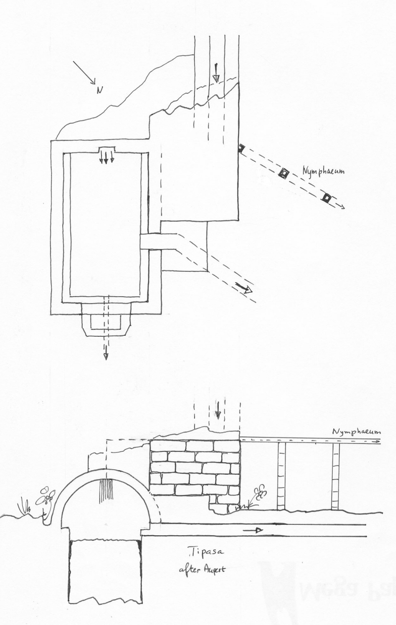
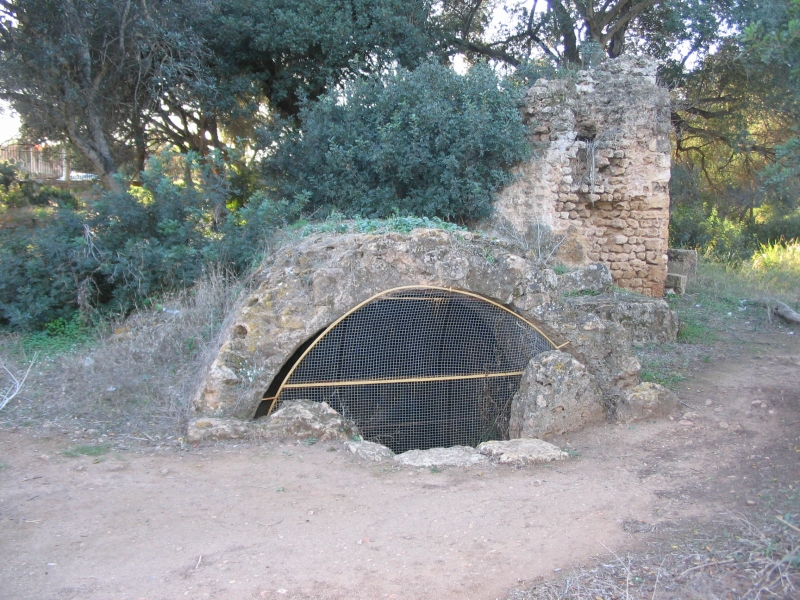
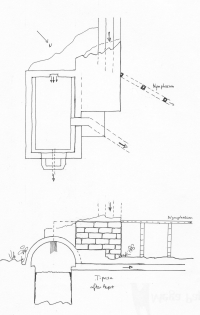
Tipasa (Algeria).
Double basin with one outlet to the wellknown nymphaeum. A second conduit brought water to a settling basin with one major outlet plus a small drain (?) (after Aupert 1974) |
 |
 |
|
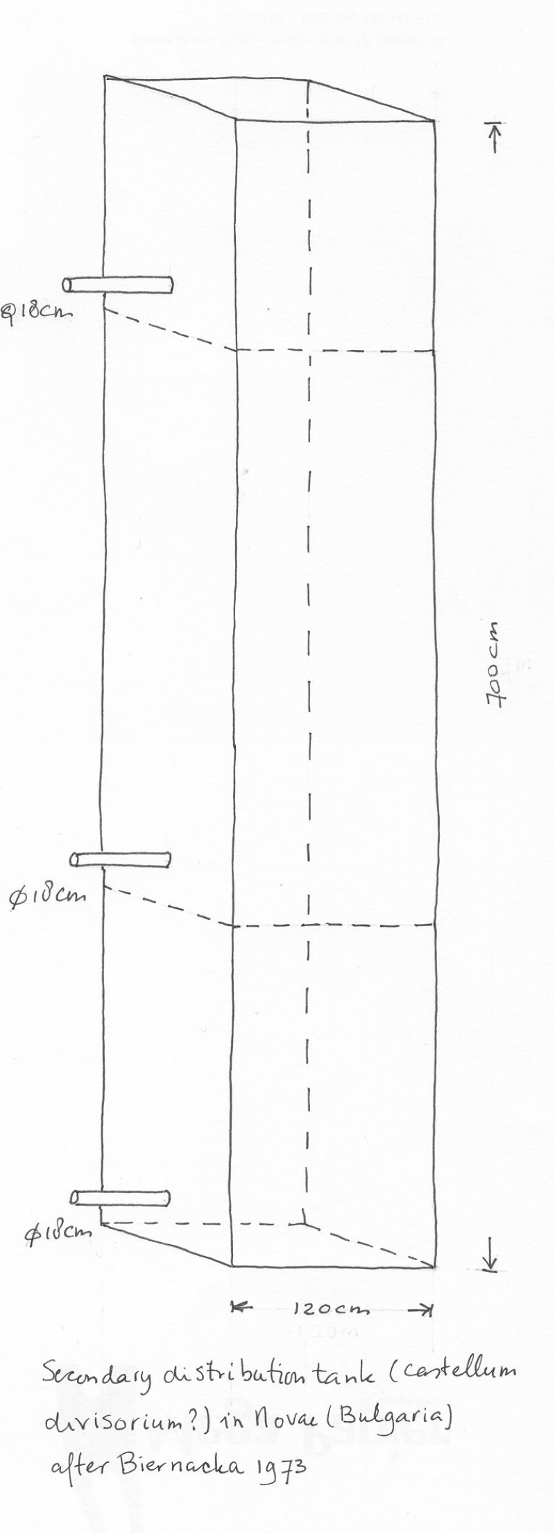
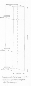
Sviscov - NOVAE (Bulgaria).
Ssecondary distribution basin
Tarnovo area. Close to the windmill Slavjanka in the NW corner of the city. Discovered in 1915, archaeological work in 1961/1962.
A lead basin height 7 m, sides of 1,2 m, built on a brick platform next to its origin in the neighbourhood of the windmill Slavjanka. The basin was protected against seasonal flooding by underground water by two parallel protective walls (they bare remains of two reconstructions necessary because of erosion by underground streams).
The basin played also a role in cleaning the water because its pipes had nets stopping all pollution. The diameter of the pipes was 0,18 m (biernacka 1973).
|
 |
|
|
| C |
 |
|
|
| Description |
Line drawing |
Photo |
Extra |
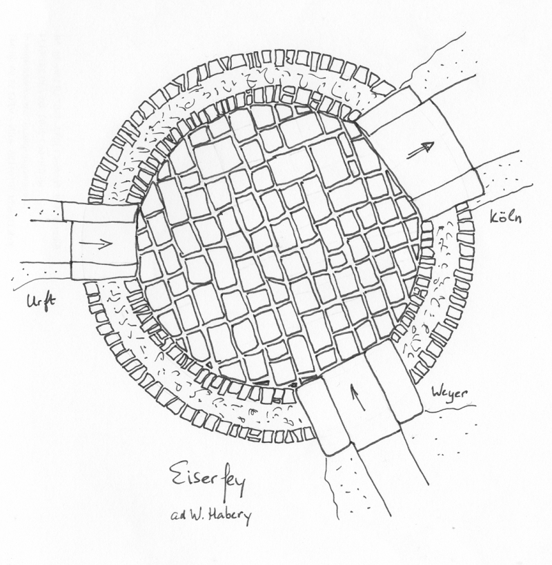
Köln / Cologne - CCAA Germany).
Eiserfey, basin in the aqueduct of Cologne. The aqueduct came from Grüner Pütz via Urft (left) heading for Köln (top right). An extra - not that big - feeder line came in from Dreimühlen. |
 |
 |
 |
Paris - LUTETIA (France).
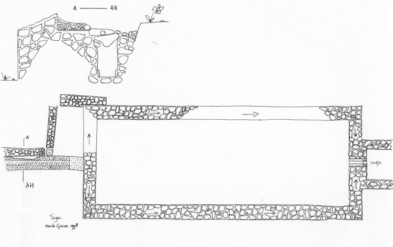
Wissous, start of the aqueduct of Paris. Three feeder lines came together in a square basin with a lowered floor for decantation (after Grenier 1960). |
 |
|
|
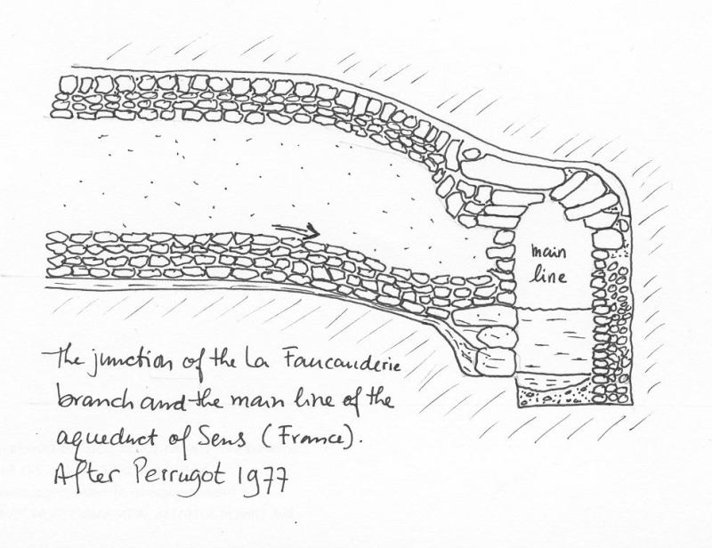
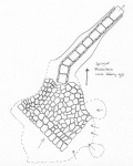
Sens - AGEDINCUM (France).
Junction of a feeder brach and the main channel, without basin (Perrigot 1977). |
 |
|
|
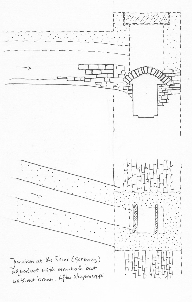
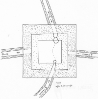
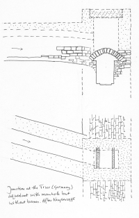
Trier - TREVERORUM (Germany).
Junction of a feeder channel with the main aqueduct, without basin but equipped with a manhole. |
 |
|
|
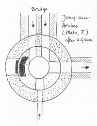
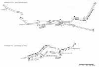
Mets - METTIS (France).
Jouy-aux-Arches. The aqueduct of Metz crossed the river Moselle by means of a 1100 m long bridge with two separate channels. Here the waters in both were combined heading for Metz (right). Note the extra small feeder channel (bottom) (after Grewe 19xx) |
 |
 |
|
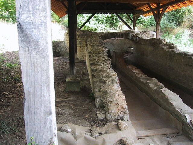
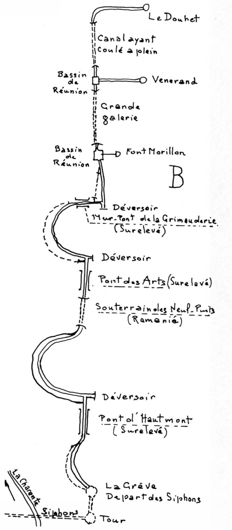
Saintes - .... (France).
Just upstream of three bridges sluice gates were places in side branches as
regulation mechanisms. Also present: one attested and one conjectured junction basin with settling facilities
("Bassin de reunion") in the aqueduct of Saintes. |
 |
|
|
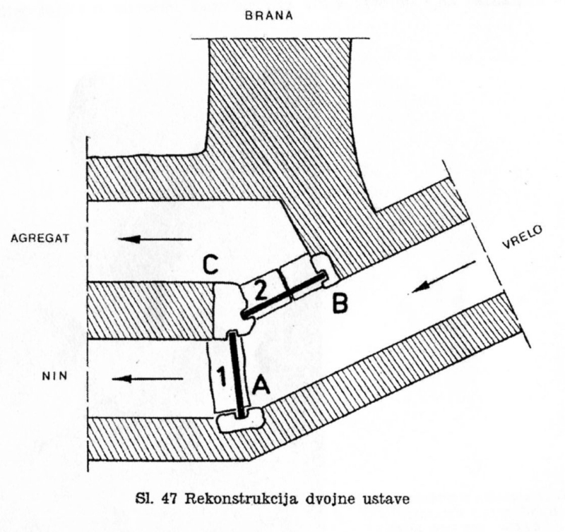
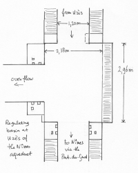
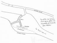
| Nin - AEONA (Croatia). Water coming from the source (vrelo) to Aeona (present Nin) could partially
be diverted to a storage basin (agregat) belonging to a mill complex. |
 |
|
|
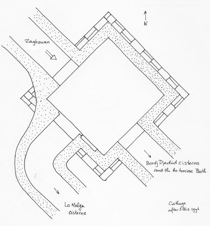
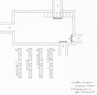
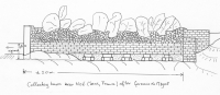
| Carthage - CARTHAGE (Tunisia) |
 |
|
|
| Rome - ROMA (Italy). Aqua Augusta (hypothetical). The hardware translation of Frontinus 14.3 by Rondelet
for the distribution of excess water of Augusta water to the Aqua Marcia and the Aqua Claudia. See the work of Germain de Montauzan (1908) |
|
|
|
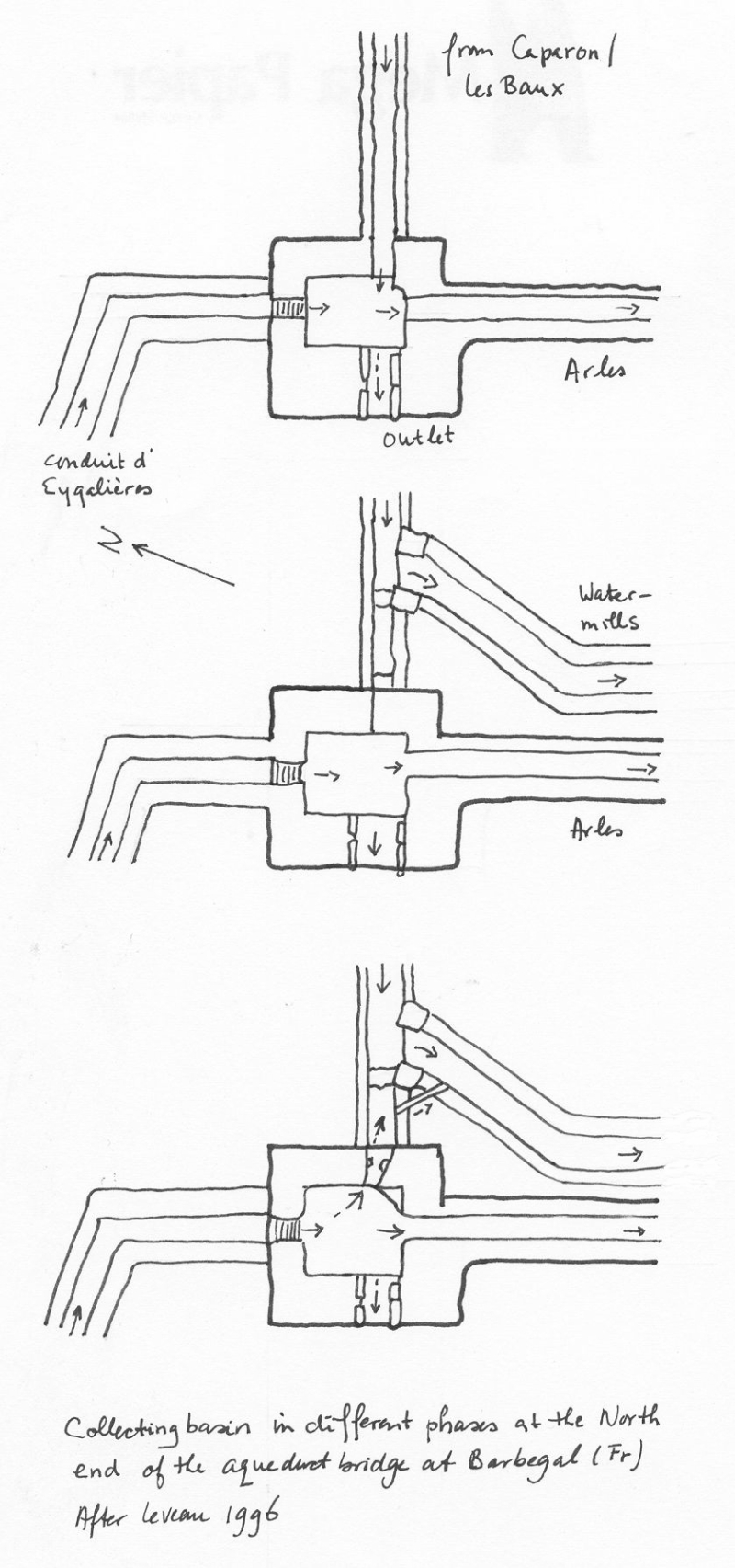
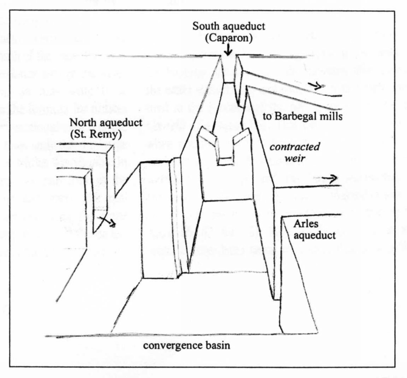
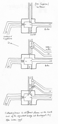
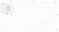
| Arles - ARELATE (France). Basin with two inlets and three outlets with a complex history in
five phases, distributing the water from the N of the Alpilles to Arles and partly to the famous grain mills of Barbegal. |
 |
 |
|
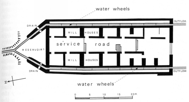
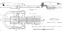
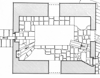
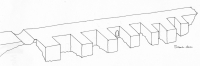
| Arles - ARELATE (France). Plan of the two times 8 grain mills of Barbegal, mainly fed by the water
of a separate aqueduct from Les Baux / Paradou (Les Alpilles). How was the water distributed amoung the two main corridors? Could one
corridor be closed during maintenance or repair? |
 |
|
|
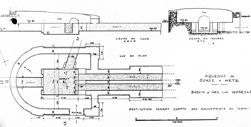
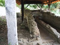
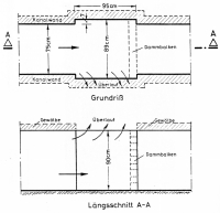
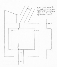
| Metz - METTIS (France) (Ars-sur-Moselle). The basin just upstream of a 1.100 m long
aqueduct bridge over the river Moselle which was crossed in two parallel channels. In the middle a deepened, square reservoir
which acted as a settling basin. One extra outlet existed which was equipped with a double set of grooves to divert surplus water. Regulation mechanisms at both main channels on the bridge are missing. |
 |
 |
|
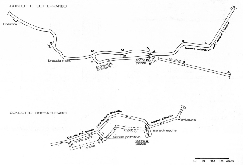
| Rome - ROMA (Italy). Gorge of San Cosimato: 'down-channel' plus sluices to facilitate the diversion of water from the Claudia aqueduct into the Marcia channel, when necessary (after Rocaioli Lamberti 1986). |
 |
|
|
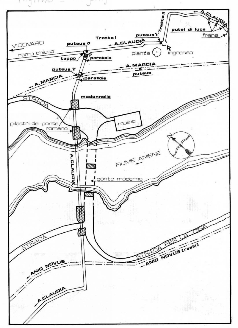
| Rome - ROMA (Italy). Start of the Hadrians loop near Madonella. At rho a splitting with a plug in the one and a sluice gate in the other branch channel. At tau a 'down-channel' for the diversion of Claudia water into the Marcia aqueduct, when necessary. |
 |
|
|
| Alcanadre -> Lodosa (Calahorra - CALAGURRIS) (Spain). A sidebranch of the aqueduct of Calahorra was equipped with three sets of grooves, problably a combination of two sluice gates (front and rear) and a filter screen in the middle. |
|
 |
|
| C |
|
|
|
| C |
|
|
|
| C |
|
|
|
| Description |
Line drawing |
Photo |
Extra |
| Metz - METTIS (France) (Ars-sur-Moselle). The basin just upstream of a 1.100 m long
aqueduct bridge over the river Moselle which was crossed in two parallel channels. In the middle a deepened, square reservoir
which acted as a settling basin. One extra outlet existed which was equipped with a double set of grooves to divert surplus water. |
|
|
|
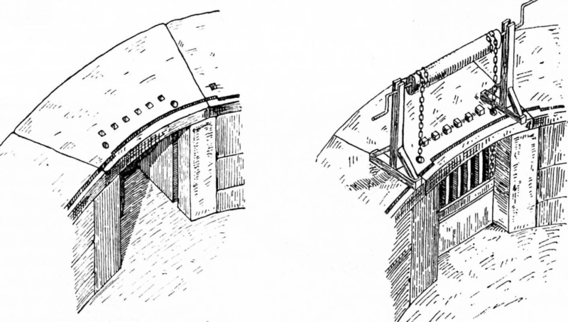
| Nimes - NEMAUSUS (France). Circular distribution basin in Nîmes, with at the inlet one set of
grooves, also in the channel floor, possibly for a movable sluice gate, chains and a windlass. |
 |
 |
|
| Nimes - NEMAUSUS (France). The Nîmes basin was also equipped with a set of three holes
for plugs or standpipes. They could have been used as drains but also as extra distribution mechanisms. |
 |
 |
|
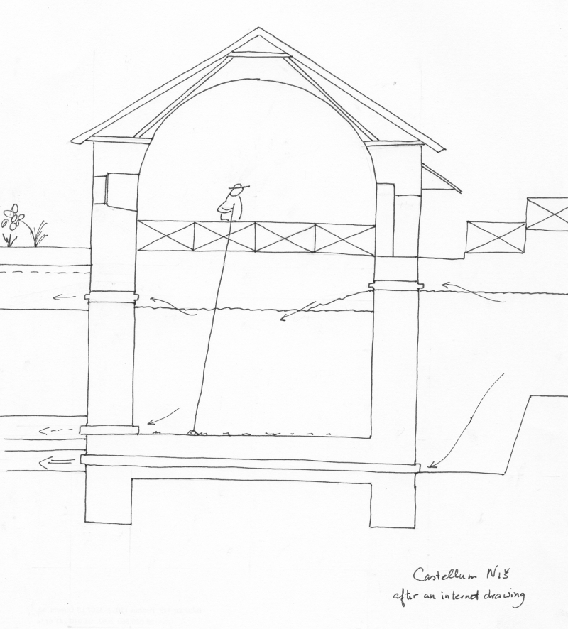
| Cologne/Köln - COLONIA CLAUDIA ARA AGRIPPINENSIUM (Germany). Complex settling and regulation basin just before the aqueduct enters the city of Köln / Cologne / CCAA. During normal operation its purpose was a settling basin which debris could be diverted by a pipe at the bottom of the main basin. To divert surplus water or to deactivate the next stretch of the aqueduct, one could by means of sluices divert the water to a river nearby. About the exact location of the sluice gates exists confusion. |
 |
 |
|
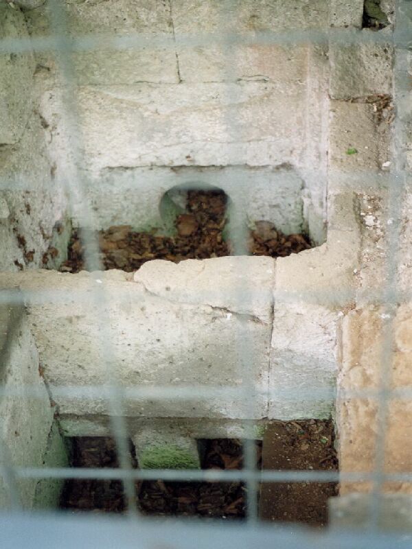
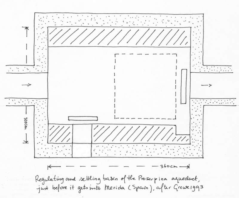
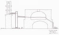
| Merida - AUGUSTA EMERITATA (Spain). Settling and regulation basin before the Los Milagros aqueduct bridge, part of the Proserpina aqueduct (after Grewe 19xx). |
 |
|
|
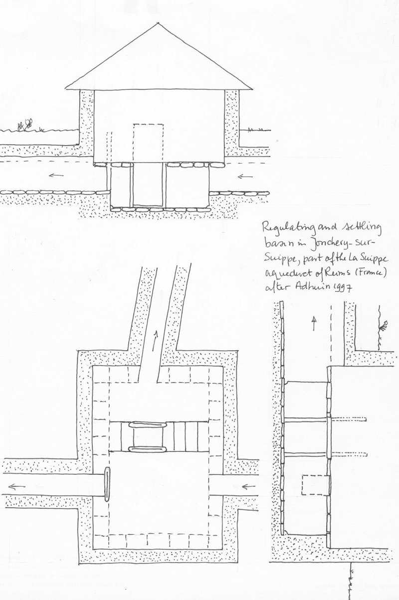
| Reims (France). Twin basin at Jochery-sur-Suippe, part of the La Suippe aqueduct of Reims, 100 m downstream of the source, with two chambers separated by an opening in the common wall. Both the outlet and the connection of the chambers were equiped with sluices (after Adhuin 1997). |
 |
|
|
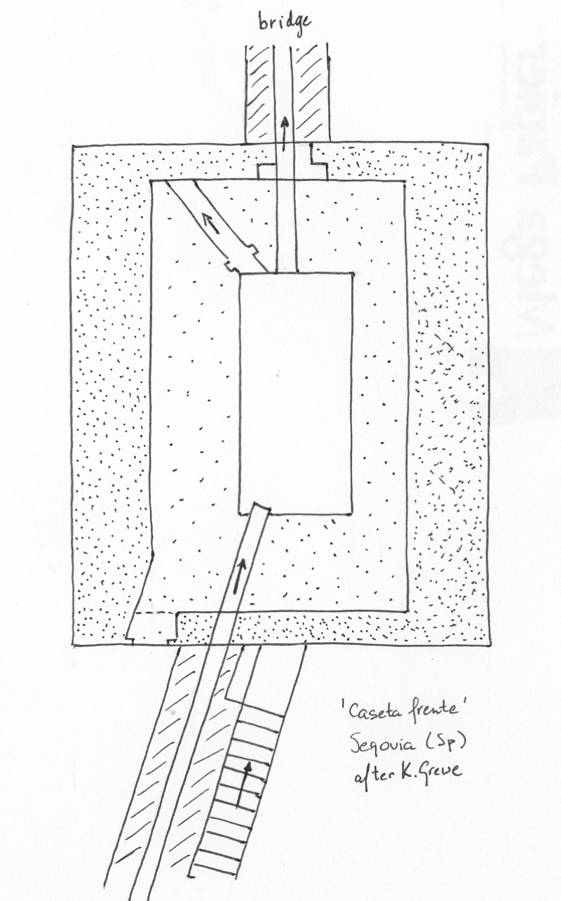
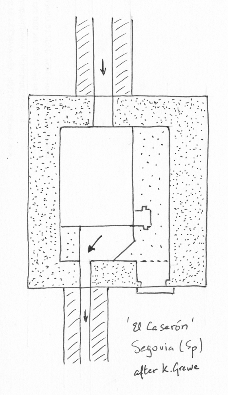
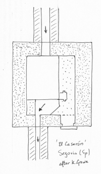
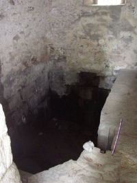
| Segovia - SEGOVIA(Spain). A regulation basin just before the aqueduct bridge in the city of Segovia. Both outlets were equipped with filtering devices. Surplus water was diverted to a stream nearby - this outlet was - contrary to the drawings - not equipped with a set of grooves |
 |
 |
 |
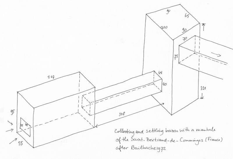
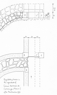
| Saint Bertrand-de-Comminges (France). A regulation facility in the auqueduct of Saint Bertrand-de-Comminges: (surplus) water could if necessary be (partly) diverted to a river nearby (left) by means of two sluices (A-B and B-C) (after Bailhache 1972) |
 |
|
|
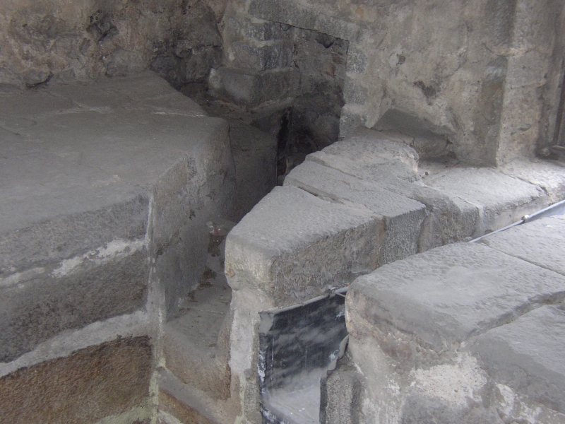
| Nimes - NEMAUSUS (France). At several places in the Nîmes aqueduct regulation basins were present
to be able to divert excess water to nearby stream, here the one at Uzès, close to the source. |
 |
 |
|
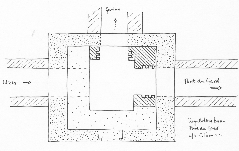
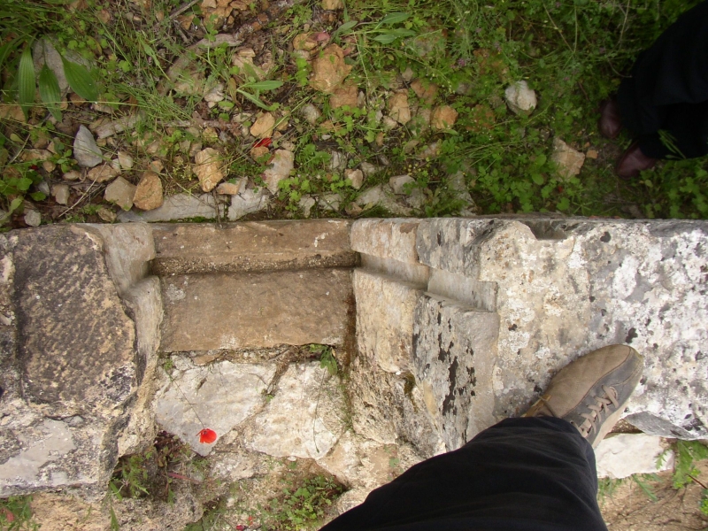
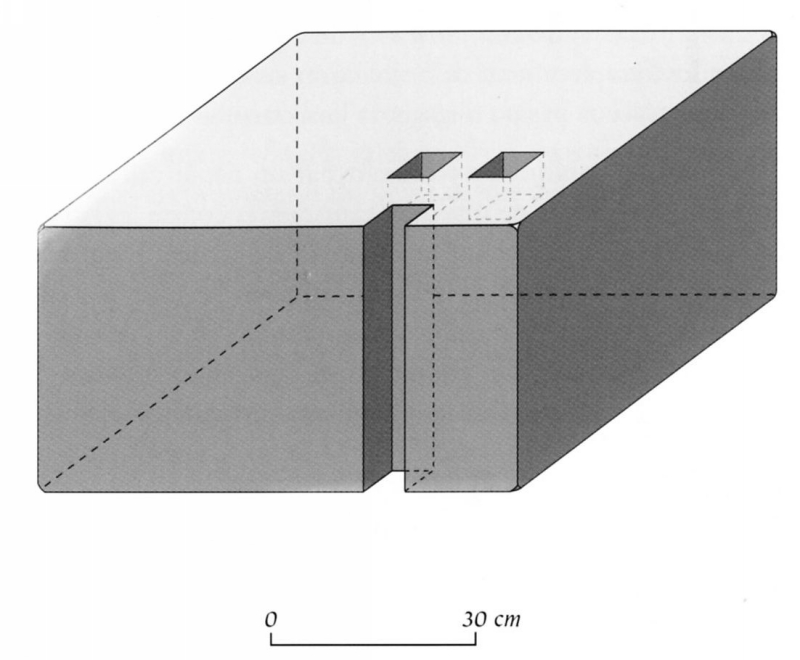
| Nimes - NEMAUSUS (France). At several places in the Nîmes aqueduct regulation basins were present
to be able to divert excess water to nearby stream. Here the one close to the aqueduct bridge called Pont du Gard. |
 |
|
|
| Frejus - FORM JULII (France). Two set of grooves in a part of the aqueduct of Fréjus
near Fondurance. The water went from left to right; at the bottom side the optional divertion to the river nearby. (From the second
set only one part is visible just over the right shoe). |
 |
|
|
| Saintes (France). Just upstream of three bridges sluice gates were places in side branches as
regulation mechanisms. Also present: one attested and one conjectured junction basin with settling facilities
("Bassin de reunion") in the aqueduct of Saintes. |
|
|
|
| Frejus - FORM JULII (France). About 50 m downstream of the original water source of the aqueduct
of Fréjus, an ancient bloc of stone was found in the riverbed of the Briancon with a groove referring to a regulation system with a sluice gate, possibly equipped with a windlass. |
 |
|
|
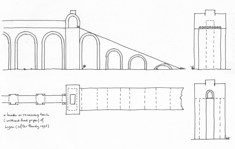
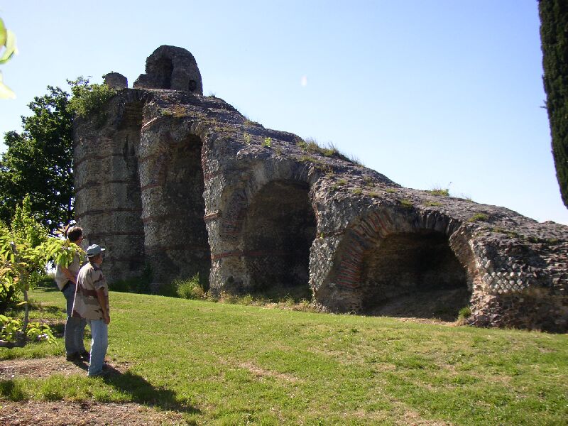
| Lyon - LUGDUNUM (France). A basin like many 'regards' in the Gier-aqueduct of Lyon but 2 x 7 cm
wider than the specus, possibly in use as a facility to block the specus by dam joists, to prevent too much pressure on the conduit upstream
during maintenance work: the water flow was diverted over the top of the basin. Note: not all archaeologists are convinced that the above is
a correct interpretation.
|
 |
|
|
| Arles - ARELATE (France)(East of Barbegal). One single set of grooves in the specus. In combination
with a second set of grooves in the wall of the specus (conjectured), this facility could regulate the water flow by diverting surplus water to
a nearby stream. |
|
 |
|
| Sens (France). Captage a Noe. Left bottom an extra supply; in the middle the collection chamber;
middle right an overflow with regulation mechanism. Arrow down left points in the wrong direction. |
 |
|
|
| Segovia - SEGOVIA (Spain). An overflow facility at the upstream side of the aqueduct bridge in the city of Segovia. |
|
 |
|
| o |
|
|
|
| Description |
Line drawing |
Photo |
Extra |
| Metz - METTIS (France) (Ars-sur-Moselle). The basin just upstream of a 1.100 m long
aqueduct bridge over the river Moselle which was crossed in two parallel channels. In the middle a deepened, square reservoir
which acted as a settling basin. One extra outlet existed which was equipped with a double set of grooves to divert surplus water. |
|
|
|
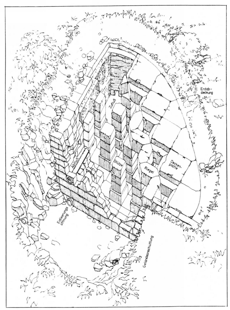
| Burnum - BURNUM (Croatia). Drawing of a storage and stettling basin based on the excavated remains of an unknown basin. Control mechanisms are possibly hypothetical (after Ilakovacs 1984) |
 |
|
|
| Cologne/Köln - COLONIA CLAUDIA ARA AGRIPPINENSIUM (Germany). Complex settling and regulation basin just before the aqueduct enters the city of Köln / Cologne / CCAA. |
|
|
|
| Rome - ROMA (Italy). A huge settling basin, part of the Aqua Virgo aqueduct op Rome. (only) Fabretti refers to this basin with four chambers in the Vicolo del Bottino near the Pincian Hill where Frontinus reports that the Aqua Virgo had no settling basins, so this basin is supposed to have been present in a side branch. Lanciani wrote that in his time (end 19th c) is was functioning as a disitbution basin. Ashby (1935) reports that the remains were destroyed by the construction of a public elevator (After Fabretti / Evans 2002). |
 |
|
|
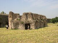
| Close to the Los Milagros bridge, Proserpina aqueduct of Merida (Spain) |
|
|
|
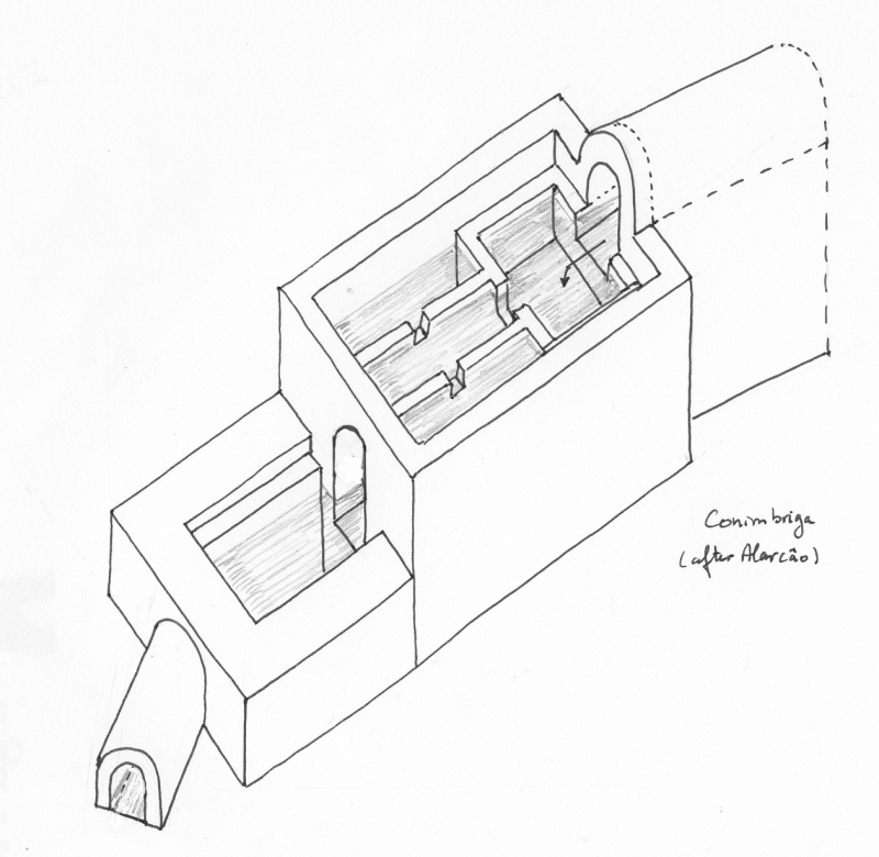
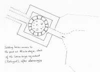
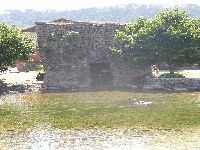
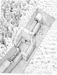
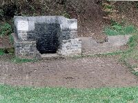
| Condeixa - CONIMBRIGA (Portugal)The pond plus tributaries at Alcabideque, the start of the aqueduct op Conimbriga, was equipped with a settling facility in an ornamental building (after Alarcao 1977). |
 |
 |
|
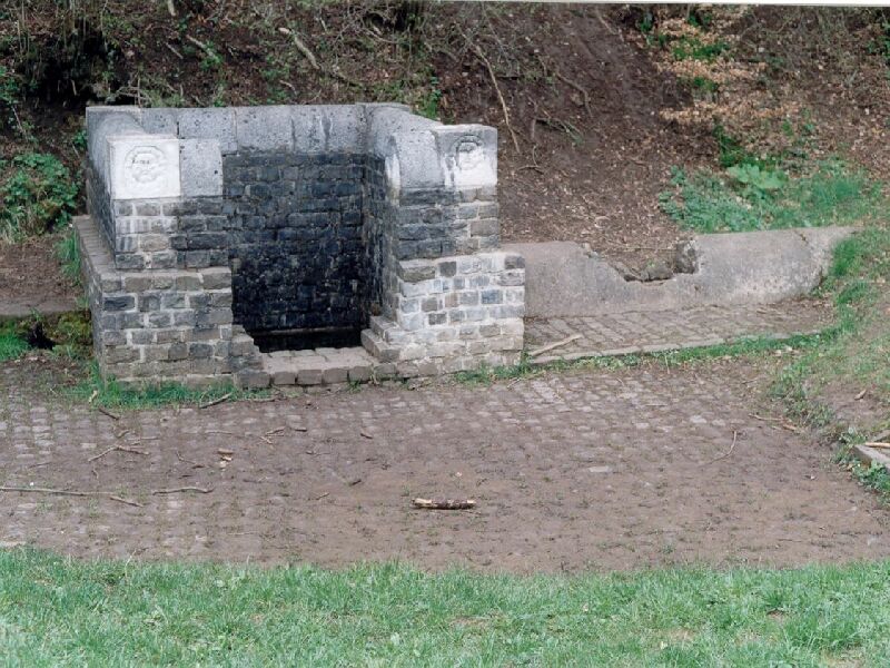
| Cologne/Köln - COlonia Claudia Ara Agrippinensium (Germany). Grüne Pütz was the start of the aqueduct of Cologne (Germany). At left a 80 meter long water collecting channel, in the middle a settling basin which was also a kind of religious site. At right the start of the aqueduct channel. |
 |
 |
|
| At one of the three aqueducts of Merida (Spain) |
 |
|
|
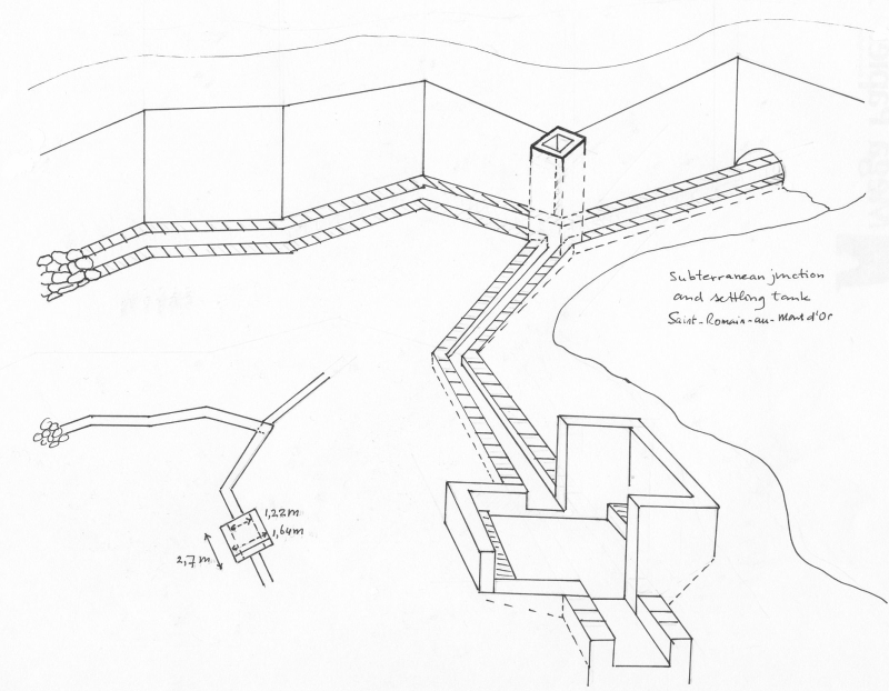
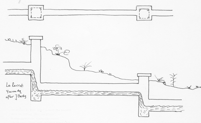
| Lyon - LUGDUNUM (France). At the start of the Mont d'Or, one of the four aqueducts of Lyon. First a subterranean junction with manhole but without control mechanism, followed by a setting facility (after Burdy 1987). |
 |
|
|
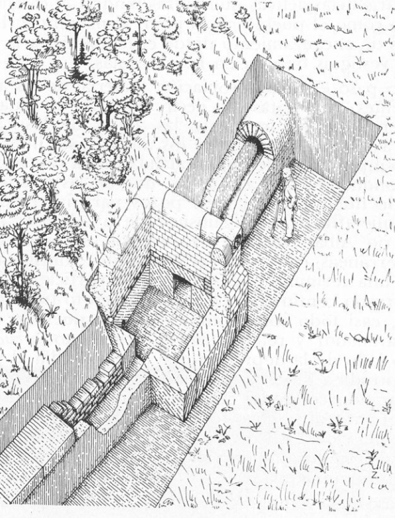
| Nis - NAISSUS (Serbia). An unknown basin th the aqueduct of Niš (Serbia) suggesting a storage or settling basin with drain or outlet. To prevent problems with the ground water an extra drain under the building was built. |
 |
|
|
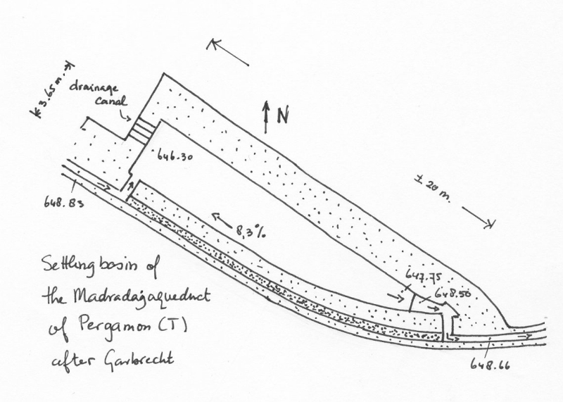
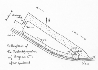
| Pergamon - PERGAMON (Turkey). A settling basin was added (see the trace of the original channel) with drain (upper left) (after Garbrecht xx). |
 |
|
|
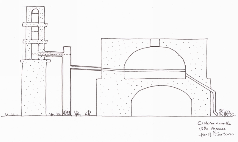
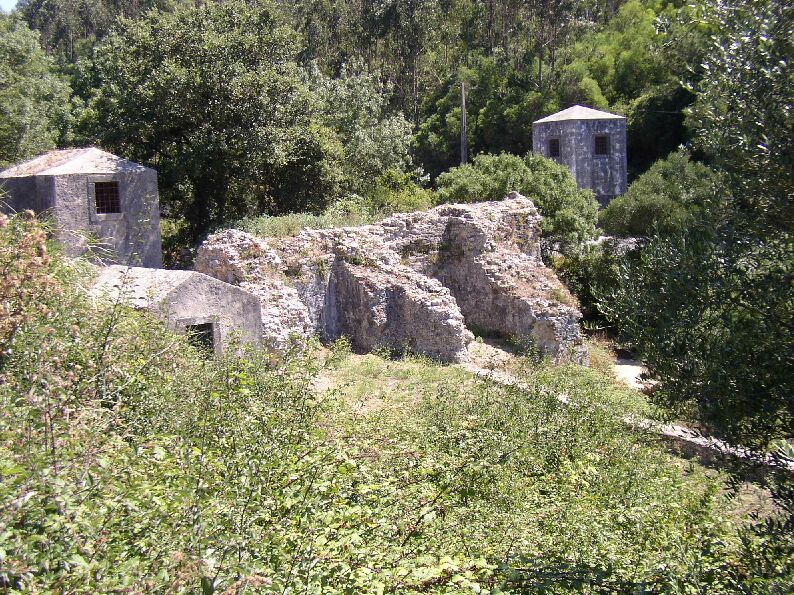
| Rome - ROMA (Italy). A tap of the Aqua Marcia, one of the 11 aqueducts of Rome, supplying the Roman villa Vignacce, in an area called Roma Vecchia, close to Rome. Note the settling facility (small tower) before the Marcia water entered the storage basin (after Pisani Sartorio 1986). Fabretti gave a detailed plan (right drawing) with a quite confusing explanation (see Fabretti / Evans 2002 pag 148). |
 |
 |
 |
| Segovia - SEGOVIA (Spain). The settling basin 1 km before the major aqueduct bridge in the city of Segovia; its drain / overflow was equipped with a nice set of grooves. View upstream. |
 |
 |
 |
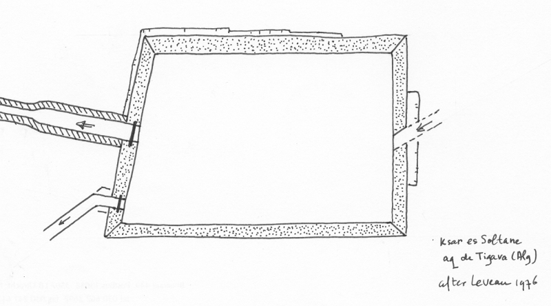
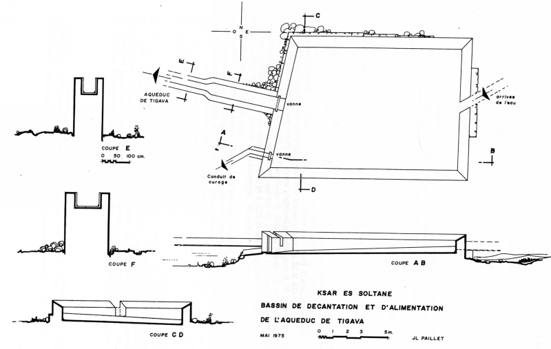
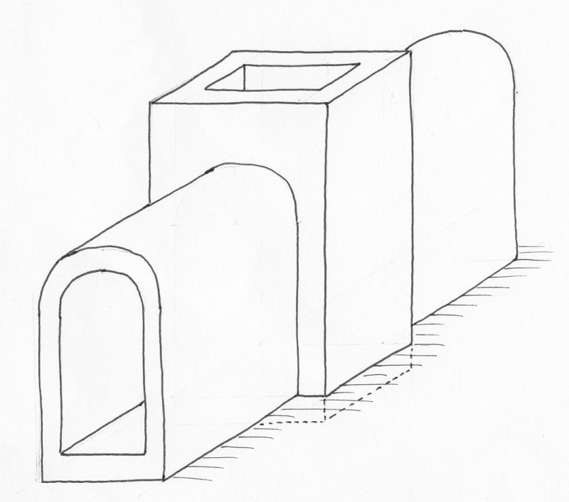
| Ksar Soltane - TIGAVA (Algeria). Settling basin with control mechanisms (sluices) both on the outlet (left) and the drain (bottom left) (after Leveau 1976). |
 |
 |
|
| Tipasa - TIPASA (Algeria). Double basin with one outlet to the wellknown nymphaeum. A second conduit brought water to a settling basin with one major outlet plus a small drain (?) (after Aupert 1974) |
|
|
|
| Lyon - LUGDUNUM (France). A typical manhole in the Gier aqueduct of Lyon, including a settling facility at the bottom. |
 |
|
|
| Reims (France). Twin basin at Jochery-sur-Suippe, part of the La Suippe aqueduct of Reims, 100 m downstream of the source, with two chambers separated by an opening in the common wall. Both the outlet and the connection of the chambers were equiped with sluices (after Adhuin 1997). |
|
|
|
| O |
|
|
|
| Description |
Line drawing |
Photo |
Extra |
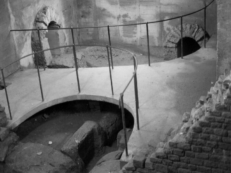
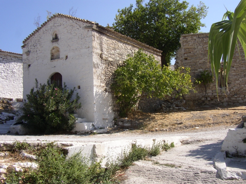
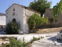
| Samos - SAMOS (Greece). Under the old church of Agiades (photo right), the water of different sources was collected: the start of the Eupalinos aqueduct of Samos. |
 |
 |
|
| Cologne/Köln - Colonia Claudia Ara Agrippinensium (Germany). Klausbrunnen was an extra source
of the aqueduct of Köln / Cologne, a rectangular water collection chamber followed by a (mini) square basin, just downstream, with an overflow.
At right the main stream from Gruner Putz comes in after passing a small settling (or stilling) basin. |
 |
 |
 |
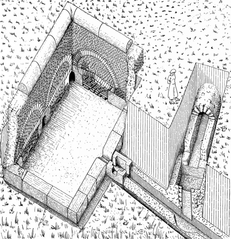
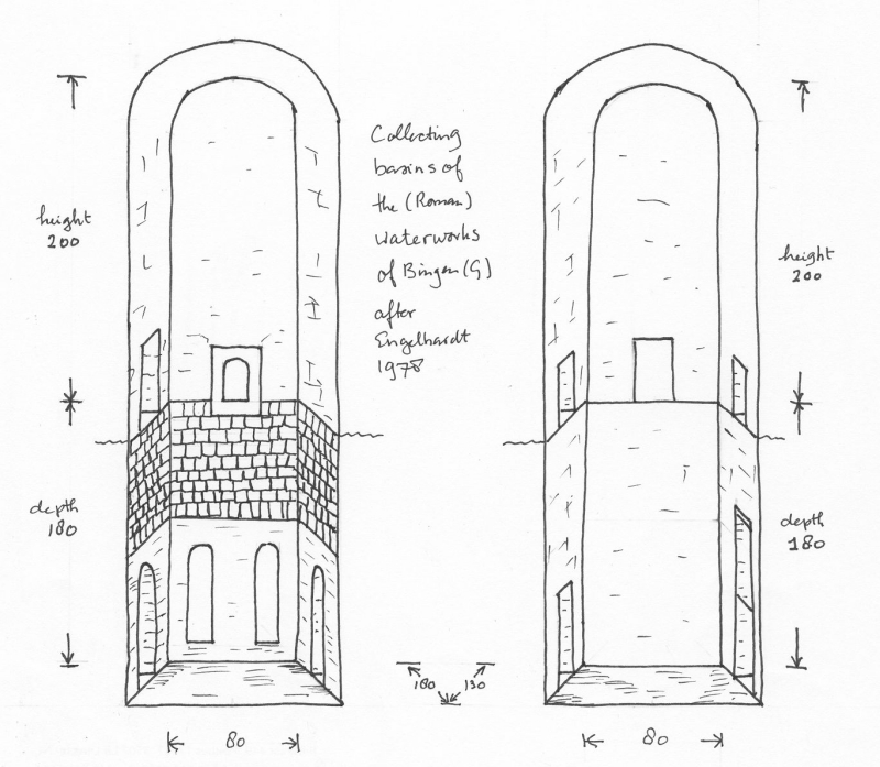
| Bingen 1(Germany) |
 |
|
|
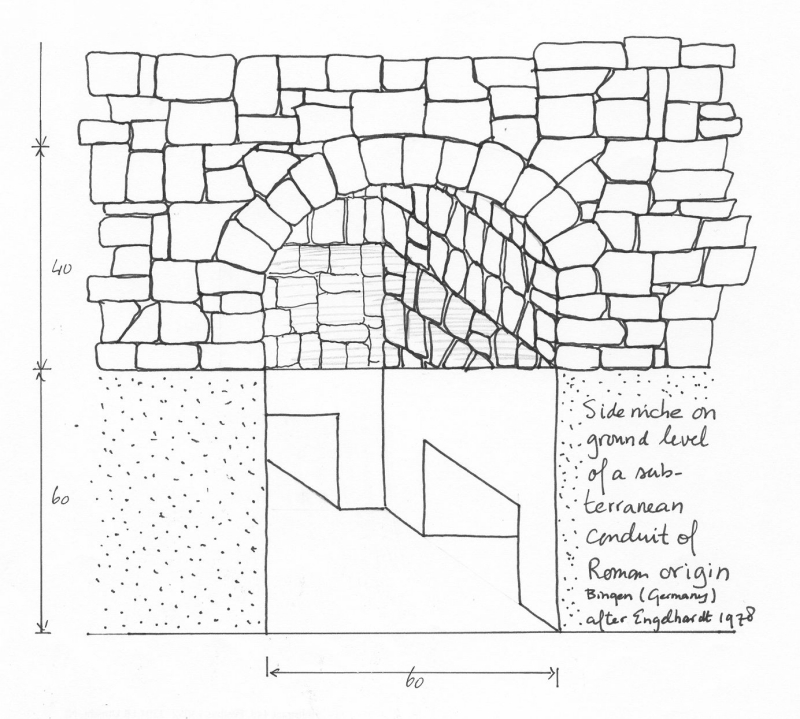
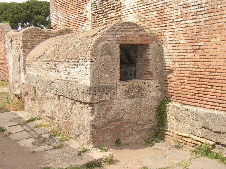
| Bingen 2 side niche(Germany) |
 |
|
|
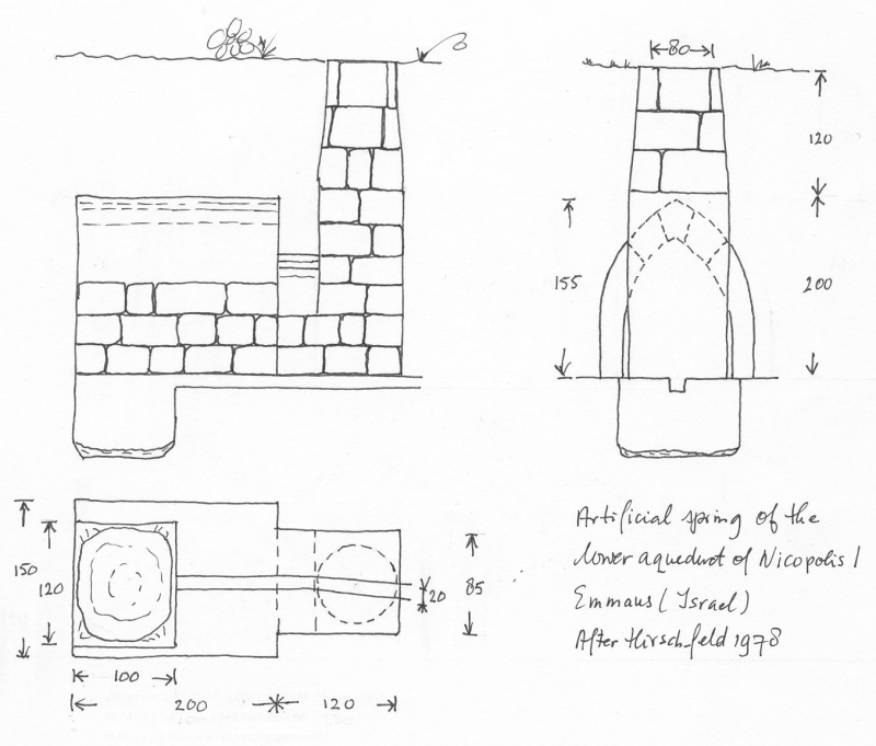
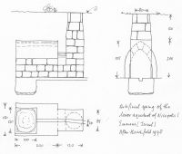
| Emmaus / Nicopolis (Israel) |
 |
|
|
| Sens (France). Captage a Noe. Left bottom an extra supply; in the middle the collection chamber;
middle right an overflow with regulation mechanism. Arrow down left points in the wrong direction. |
|
|
|
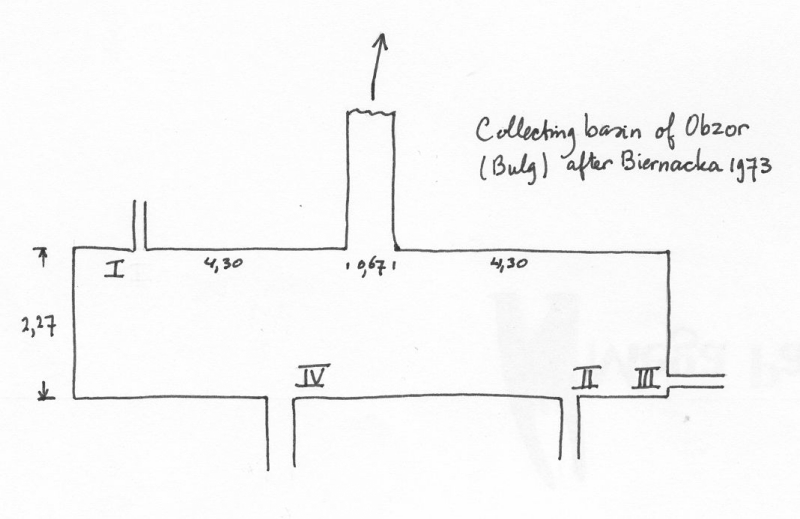
Obzor - TEMPLUM IOVIS (Bulgaria)
Burges area. Downhill of Janku Tepe and close to the SW corner of the fortress. Avaulted basin which also served as an initial reservoir,
length 9,2 m, width 2,27 m, made of bricks. The water collected came from three small sources delivered to the basin through a series of pipes.
One bigger source delivered the water through a canal built from bricks. The basin had a barrel-like dome. Its height is unknown because
the ceiling fell down. In the middel of the eastern wall of the basin there was a pipe leading the water to the aqueduct.(Biernacka1973)
|
 |
|
|
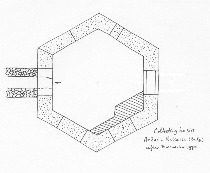
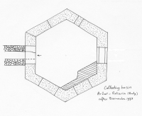
Archer - RATIARIA (Bulgaria)
Violin area. Aqueduct near Zidovec, 6-7 km SW of Archer in the neighbourhood of Varhop village; near Darzanica; at a few places near the Archer river; between Darzanica and Archer. Excavations in the year 1953 and 1965.
The hexagonal basin was built from huge stone blocks (length 2,55 m; width 0,55 m; height: first row 0,43 m, second row 0,54 m, third row 0,57 m). Only the lower two meters are preserved. The water was collected from the valley and conveyed into the open stone conduit (length 2,5 m; widt 0,43 m; height 0,65 m). The chamber walls length was on average 2,55 m. Its wide corners were made of monolitic blocks. (Biernacka1973)
|
 |
|
|
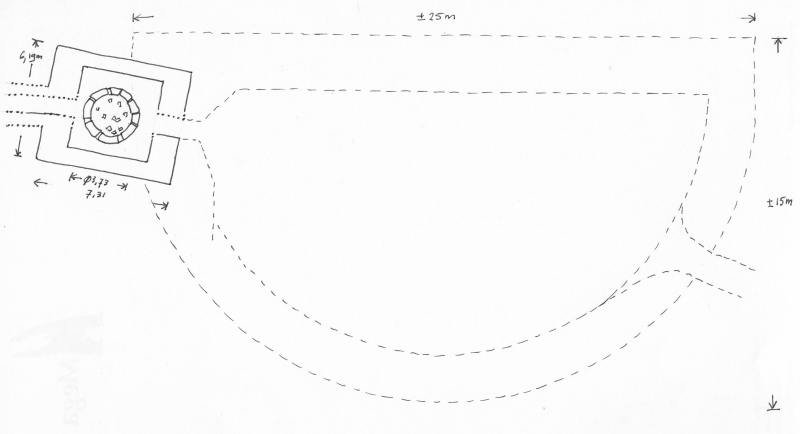
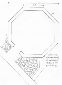
Nikjup - NICOPOLIS ad ISTRUM (Bulgaria)
Tarnovo area. Basin in Musina village. The channel follows the rivers Negovanka, Babino Deve and Rosica, Dicin village, passage across Bara, 0,5 km from the western walls of the ancient city.
This collecting basin of the water supply system was octagonal in plan, situated on the left shore of the Musinska river in front of the entrance, built from huge limestone blocks (0,60 m height, 0,55 m length and 0,25 m width), preserved till 2,5 m height. The length of the sidewalls were 1,82 m, 1,79 m, 1,72 m, 1,79 m, 1,82 m, 1,72 m and 1,72 m. The corner steadies of the basin were made of monolith two-arm stones, creating obtuse angles kept together by iron staples. In the basin walls were two openings, the first one was used conveying the water to the water supply system, the second one to discharge excess water.
The remains of the water supply channel made of bricks and discovered in Musina village, indicate that the channel was built of slack laid, in the wall core, in broken stones welded with white mortar. The height was 1,2 m, the width 0,6 m. The inside was covered with hydraulic mortar - 0,02 m thick. In a few places the existence of inspection holes covered with tetragonal stone plates was proven. (Biernacka1973)
|
 |
|
|
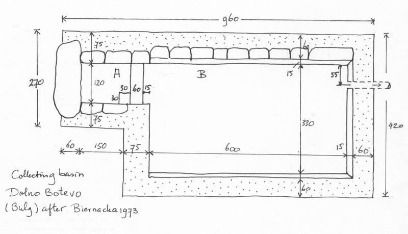
Dolno Botevo (Bulgaria)
Haskovo area. At the Cala hill, 1 km N from the village. Excavations in 1958.
A. A four sided basin (1,20 * 1,50 m, height 0,90 m) which bottom was built of natural stone. The side walls were made of stone blocks reinforced from outside with a supporting wall, 0,45 m thick, made of broken stones. On the top the basin was covered with flat stone slabs.
B. The main reservoir, size 6,0 * 3,3 m, was built on rocks covered with red hydraulic mortar, 0,2 m thick. The lower parts of the walls were made of broken limestone covered with mortar; the upper parts ware made of bricks, except the eastern wall which was built of stone blocks. In the SE corner there was a step (height 0,85 and 0,15 m wide). Internally the walls were covered with red, hydraulic mortar, 0,02 m thick.
Opposite basin A which was separeted from basin B with a stone step there was a clay pipe (diameter 0,15 m) leading the water to the aqueduct. Inside the basin many big tiles were found. The whole object including the water source was completely destroyed when a new basin was built in the IVth century. The E wall was reconstructed in recent times. (Biernacka1973)
|
 |
|
|
| Arles - ARELATE (France). Basin with one inlet and three outlets with a complex history in five phases, distributing the water from the north of the Alpilles to Arles and partly to the famous grain mills of Barbegal. |
|
|
|
| Noé basin, aqueduct of Sens (France) |
 |
|
|
| Saint Bertrand-de-Comminges (France). Regulation basin, 28 m from the source of the aqueduct
of Saint-Bertrand-de-Commignes - to divert excess water to a stream nearby. |
 |
|
|
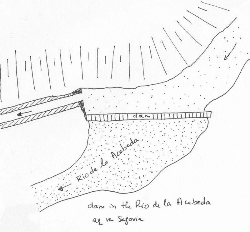
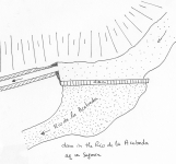
| Segovia (Spain). The start of an aqueduct. The water of the Rio de la Acebeda was partially diverted into the aqueduct channel towards Segovia via a moveble sluice gate. |
 |
 |
|
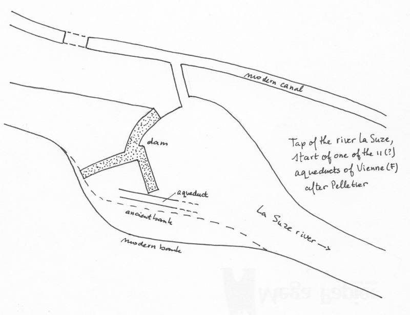
| Start of one of the 11 aqueducts of Vienne |
 |
|
|
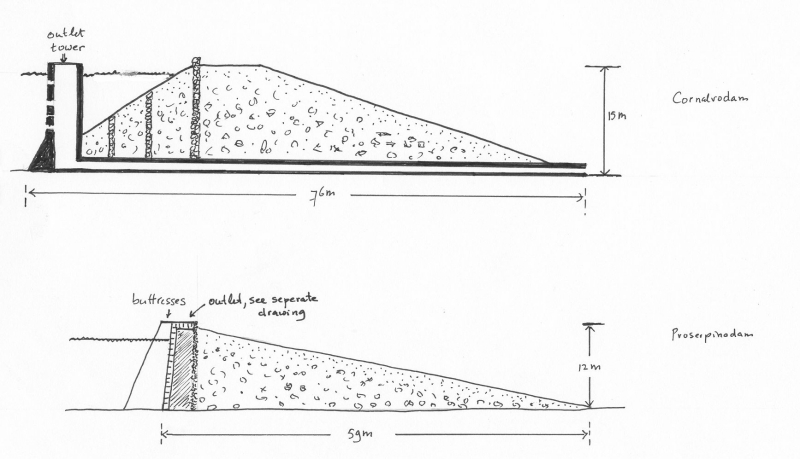
| Hypothetical dam including spill-over |
 |
 |
|
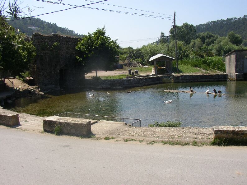
| Alcabideque, start of the Conimbriga aqueduct (Portugal) |
 |
 |
|
| Start of the aqueduct of Glanum (France) |
 |
|
|
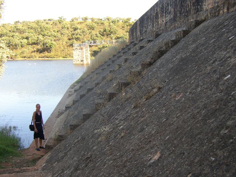
| Two dams in the Merida region (Spain) |
 |
 |
|
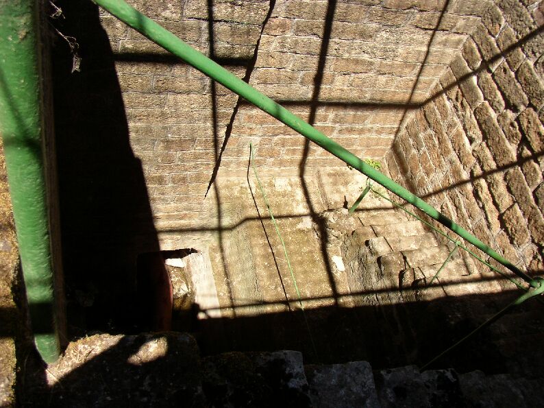
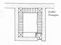
| Outlet of the Proserpinadam (Merida - Spain) |
 |
 |
|
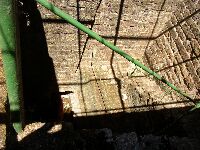
| Detail outlet Proserpinadam (Merida - Spain) |
 |
 |
|
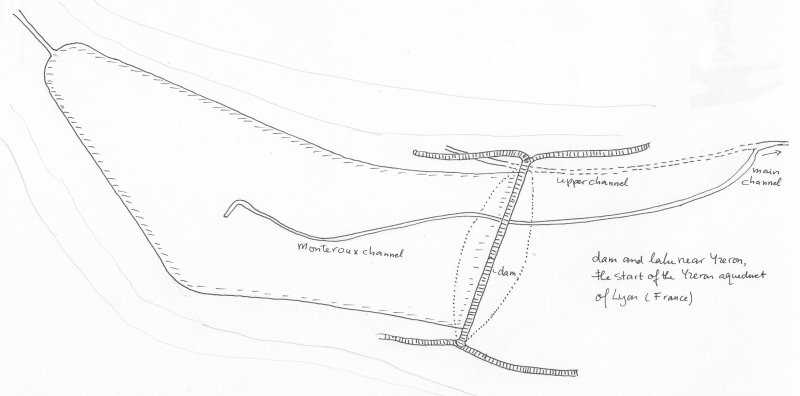
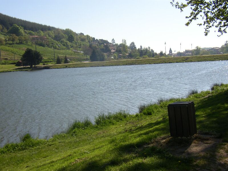
| Start of the Yzeron aqueduct (Lyon - France) |
 |
 |
|
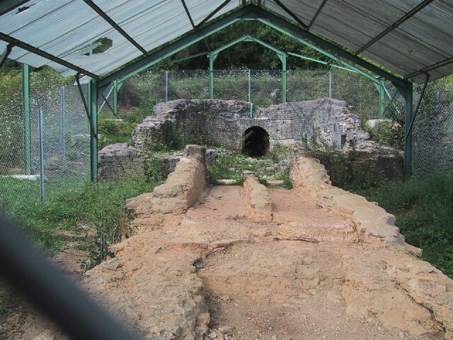
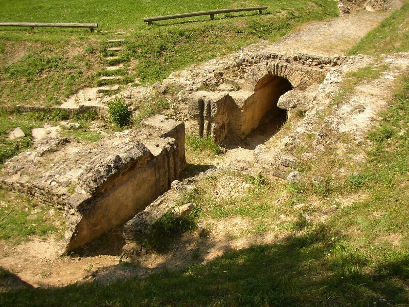
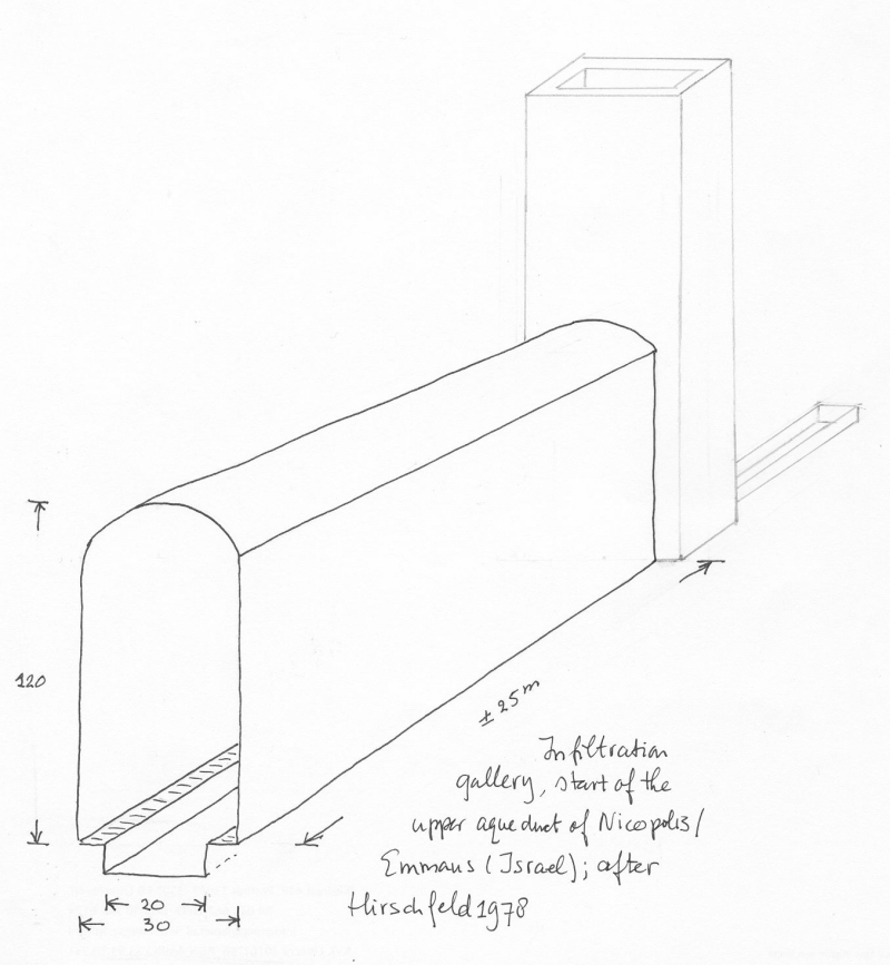
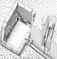
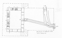
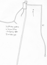
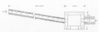
| Emmaus -NICOPOLIS (Israel). Infiltration gallery plus manhole, start of the upper aqueduct of Nicopolis (after Hirschfeld 1978). |
 |
|
|
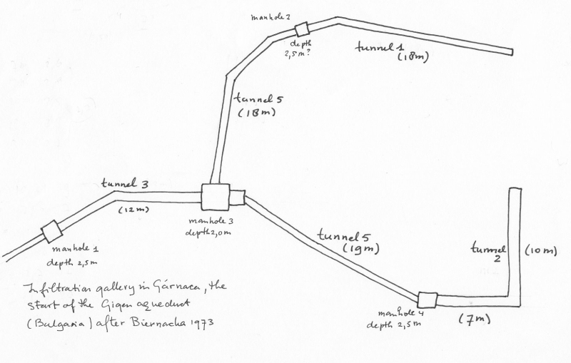
Gigen - OESCUS (Bulgaria), infiltration gallery
The catchment area in Gárnica was discovered during the construction of the present wells for Gigen.
In the hills SE of Gigen there was a tunnel system of irregular, multiflank shape (total length over 80 m). The tunnel width varied from 0,5 - 1,0 m, the average height was 1,60 m (ranging from 1,35 - 1,7 m), its top was vaulted, 0,15 m height. The tunnel was built from big stone blocks (length 0,43 m, height 0,2 m). Via holes the water poured out of the walls. In September 1965 the water level was 0,58 m above the floor. The four chambers had provisional steps (height 0,19 m, width 0,14 m, depth 0,21 m). Annex to chamber nr. 3 there was a four sided room (lenght 1,9 m, width 1,8 m, height 2 m) serving as an initial / collecting reservoir. From that point the water went through a small stone pipe (0,2 * 0,3 m) into the aqueduct.(Biernacka1973)
|
 |
|
|
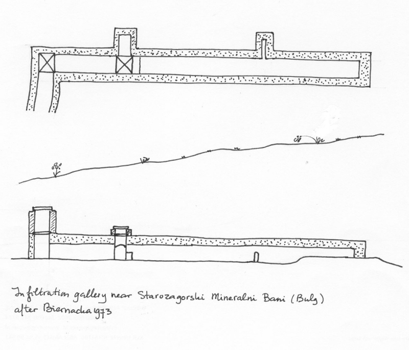
Starozagorski Mineralni Bani (Bulgaria)
area of Stara Zagora, 25 m E from the present women toilet. Discovered in 1937, archaeological work in 1965.
The tunnel intake was built in the letter 'L'. Its length was 19 m, 0,7 m width and 1,5 m height. The walls were made of bricks, the middle part of the ceiling made of stone. The tunnel had two side-chambers which collected water from smaller niches attached to the main water supply. The tunnel basis was made of big broken stones, cut in the middle with bricks laid in three rows. (biermacka1973) |
 |
|
|
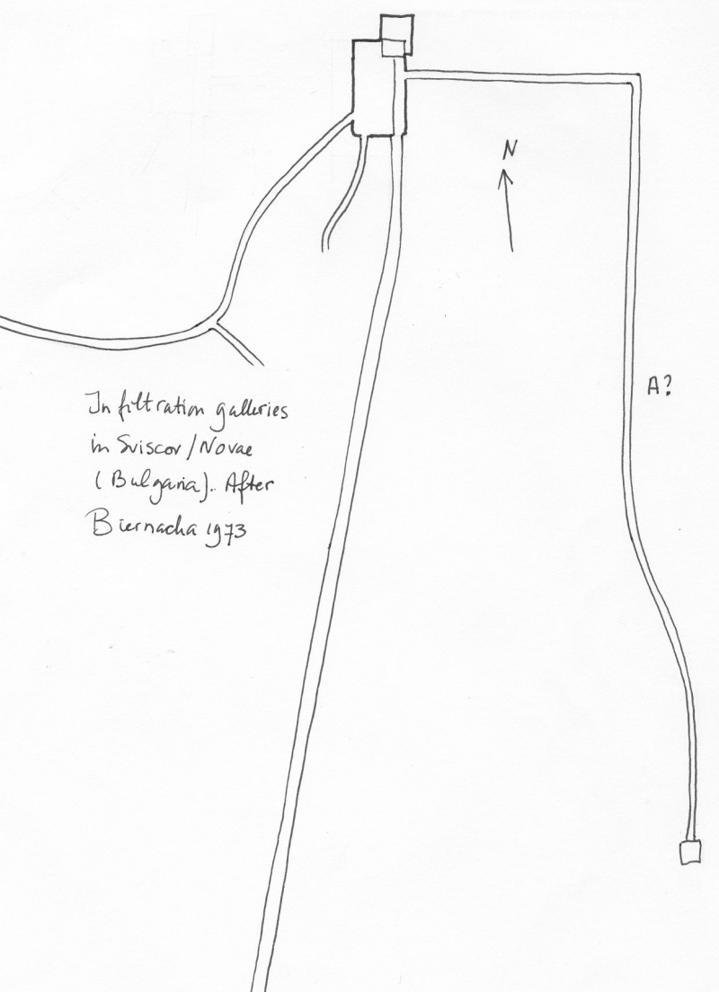
Sviscov - NOVAE (Bulgaria)
Tarnovo ares near the buildings of Zaklad Naprawczy Maszyn Rolniczych; southern city gate. Excavations in 1965 and 1966.
Remains of a wall belonging to a tunnel like a Roman water intake, adapted in Turkish time. The present remains are in tunnel 'A' (??) in the floor which, next to the entrance, also holds a small square basin built of bricks.
|
 |
|
|
| Cologne/Köln - Colonia Claudia Ara Agrippinensium (Germany). Grüne Pütz was the start of the aqueduct of Cologne (Germany). At left a 80 meter long water collecting channel, in the middle a settling basin which was also a kind of religious site. At right the start of the aqueduct channel. |
 |
|
|
| Miesenheim (Germany). Infiltration basin, start of an aqueduct, near Miesenheim (after Habery 1971). |
 |
|
|
| Lyon - LUGDUNUM (France). At the start of the Mont d'Or, one of the four aqueducts of Lyon. First a subterranean junction with manhole but without control mechanism, followed by a setting facility (after Burdy 1987). |
|
|
|
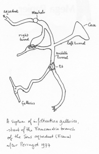
| Sens (France). A system of infiltration galleries, start of the Faucandrie branch of the aqueduct of Sens (after Perrugot 1977). |
 |
|
|
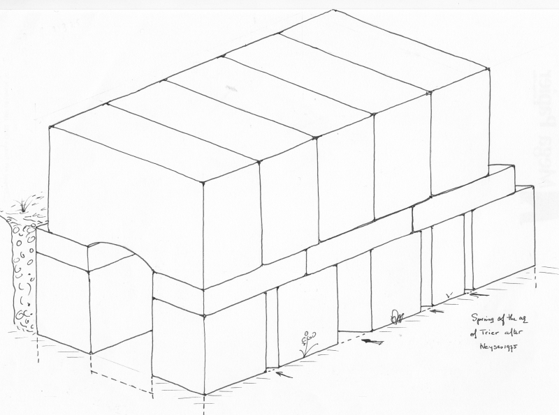
| Trier - Treverorum (Germany). Hypothetical drawing of an infiltration gallery, start of the Trier aqueduct (after Neyses 1975). |
 |
|
|
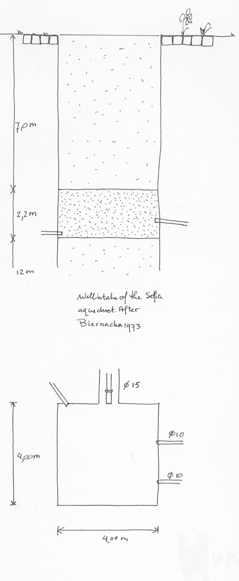
Sofia - SERDICA (Bulgaria), Well intake
Banski square; next to the NW corner of the Central Universal Warehouse. Excavations in 1955.
A stone well discovered under the Turkish one during the construction of a modern well. The Roman well was built in a square plan (4x4 m), its height was 2,95 m. The walls were made of bricks. In the northern wall there was a clay pipe (diameter 0,22 m) leading to a canal built of bricks. After passing a narrowing the water went further in a lead pipe (diameter 0,15 m). From the E and N walls some other lead pipes came in. Inside the lower part the basin was covered with two layers of grind. Built in the third century. (biernacka1973)
|
 |
|
|