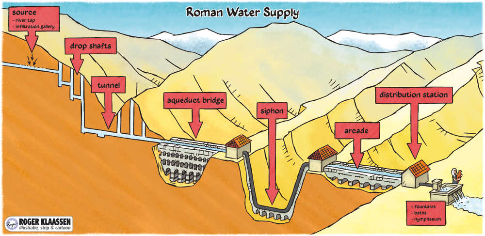
1. Main elements en terms of Roman aqueducts


Note that commonly the complete aqueduct system - from the source to the distribution basin, with channels or pipes - is called an aqueduct. Bridges like the world famous Pont du Gard near Nimes (France) and in Segovia (Spain), are called aqueduct bridges.

General literature
- A.Th. Hodge (1992, 2002): Roman aqueducts and water supply
- A.I. Wilson (2008): Hydraulic engineering and water supply (in: J.P. Oleson: The Oxford Handbook of engineering and technology in the classical world (2008) pag 285 - 318)


The main elements in four languages
1. Source
2. Dropshafts
3. Settling tank
4. Tunnel and shafts
5. Covered trench
6. Aqueduct bridge
7. (inverted) Siphon
8. Substruction
9. Arcade
10. Distribution basin
11. Water distribution (in the town)


1. Source
There are many ways to get (ground)water into an aqueduct. The most common ones are: 1. Spring boxes and well intakes, 2. Infiltration galleries, 3. River intakes, 4. Dams.
Springs were the commonest source for roman aqueducts. River intakes were used occasionally (often because of fear of pollution). Artificial created lakes as a source were rare although they could have been used to equalize the variations in the seasonal flow rates of the feeding spring.

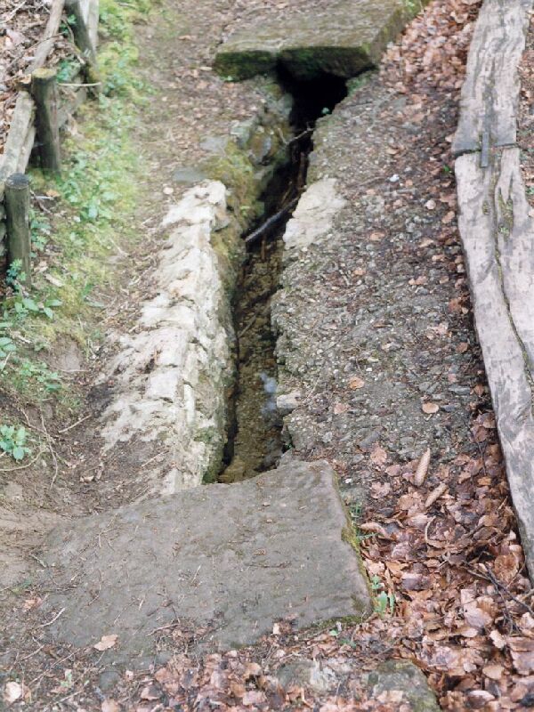
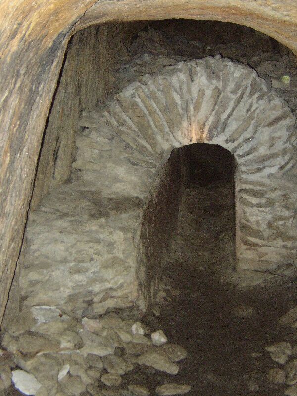
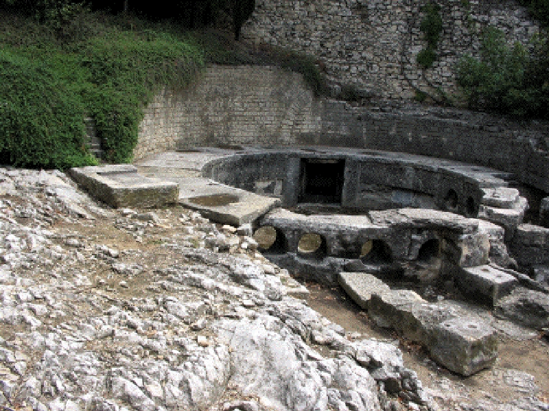
Photo: Infiltration gallery at Grüner Pütz, one of the sources of the aqueduct of Köln (Cologne, Germany).
2. Dropshaft
In some cases however, when the source is high up in the hills, it is necessary to make the aqueduct steep. In such cases special constructions are needed to avoid damage, sometimes in a cascade setting. The best known examples were the subterranean dropshafts of Le Recret in the Yzeron aqueduct of Lyon (France) and the ones on the Montjeu aqueduct of Autun (France). Sometimes smooth chutes or stepped cascades were used, to dampen wave energy, often in combination with a stilling basin.
3. Settling basin
Settling basins were built to get rid of all kinds of pollution and were mostly situated near the source of an aqueduct and / or near the end, just before the terminal castellum divisorium, the water distribution centre of a town or villa. Some basins had a special outlet to discharge the dirt, in other cases the debris had to be removed periodically by hand. The best known examples were at the aqueduct of Cologne (Grüne Pütz, Germany) and Rome (a 4 chamber basin in a side branch of the Aqua Virgo, as drawn by Fabretti).

Photo: A small settling basin with overflow (middle bottom) at Kallmuth, near one of the sources of the aqueduct of Köln (Cologne, Germany).
4. Tunnel and shafts
To prevent detours a tunnel could be necessary. For a number of reasons (to prevent lining problems - there are odd examples of miscalculations in aqueduct tunnels - to save time and to make more economic use of the labour force etc) the Romans often used the qanat way of tunnel construction in which multiple vertical shafts were dug over a hill top after which the bottom of the shafts were connected with each other. The longest Roman tunnel, as far as we know, is the Mornant tunnel in the Gier aqueduct of Lyon (France): 825 meter long. There may have been a 2250 meter long aqueduct tunnel in the Anio Novus aqueduct of Rome using Qanat techniques.

Photo: Cave de Cureé tunnel in the Gier aqueduct of Lyon (France)
5. Covered trench
Almost 80% of all Roman aqueducts were laid subterranean by 'cut and cover' technique. The easiest way was 1) to dig or hew a trench, 2) to build a channel or lay down pipe, and 3) to cover it up.
For a cross-section see separate
drawing.
6. Aqueduct bridge
To 'bridge' a gap in the terrain and to prevent a long detour, especially to cross a valley or a river, a bridge for the aqueduct conduit was built. The highest bridge almost 50 meters above the river Gardon is the famous Pont du Gard, part of the aqueduct op Nîmes (France), but there are many more examples. In the case of the Metz aqueduct (France) a double channel crossed the Mosel river on one bridge.

On the picture two almost parallel bridges in the valley of the river Le Reyran, north of Fréjus (France), one replacing the other because of stability problems.
7. Siphon
Where a valley to be crossed was too deep or too big for a bridge, a siphon was built. The aqueduct water ran into a distribution tank, often called header basin. A row of parallel (lead) pipes (e.g. 9) left the other side of the tank and descended into the valley, crossed the bottom on a so called 'venter' bridge and climbed up to the other side to the 'receiving' basin from which the water continued in a masonry channel to its destination.

Photo: The receiving basin of the Brévenne siphon, part of the Brévenne aqueduct of Lyon (France).
8. Substruction
Sometimes extra walls were built to get the right level for the conduit. This was only done for a height less that 2 meter.

Photo: Substruction in Soucieu in the Gier aqueduct of Lyon (France).
9. Arcade
To get the aqueduct on a higher position than 2 meters, a series of arches was built. The best know examples are found in the area of Rome

Photo: The double aqueduct Aquae Claudia and Anio Novus in the archaeological park near Romavecchie, 15 km SE of Rome (Italy).
10. Distribution basin
At the end of a gravity flow aqueduct a distribution basin (castellum divisorium) was built, located in the upper part of a town or near a villa. Vitruvius made a description of such a basin, but the few basins which were excavated had different characteristics (!).

Photo: The well-known water distribution basin in Nîmes (France).
11.Water distribution
From the distribution basin the water was led by means of lead or terracotta pipes to street fountains, baths buildings, ornamental fountains (nymphaea) and sometimes to private users. In some cases the water in the town was first subdivided in second order castella and from there on it ran to its users.

Photo: One of the street side fountains along the main road of Gerasa (Jerash, Jordan).


HOME More literature on more aqueducts Last modified: April, 2016 - (webmaster)