Municipal water supply in antiquity
a historical introduction
Prof. dr. Henning Fahlbusch, Fachhochschule Lübeck, Germany
Summary
Since the beginning of early cultures men not only used natural water resources but also improved them by artificial methods. Based on observations of nature they constructed
small and large storage basins for a temporary transfer of water from a period of rich supply to one with scarce supply but big demand. The method of a local transfer diverting water
to the place of demand was also invented very early. The technological development especially of this kind of transfer is roughly outlined. Examples are given for the
different elements of ancient water supply systems.
General
Each settlement of men depends on a sufficient water supply. This applies especially for the arid and semiarid climate in the regions around the Mediterranean and the Near East
where water is extremely scarce in summer. But in these regions the first cultures rose. In the following the main elements of municipal water supply will be presented
as well as their artificial development by men including the combination of different methods. Examples will be presented from prehistory up to Roman times.
Local Supply
The water demand of the first small settlements and villages probably was covered by local sources. Subsurface water could be used from perennial flowing rivers
(i.e. Nile, Euphrates, Tigris etc.) or lakes.
Naturally this water is and not seldom was contaminated. On the other hand water from springs often is much purer, cooler and
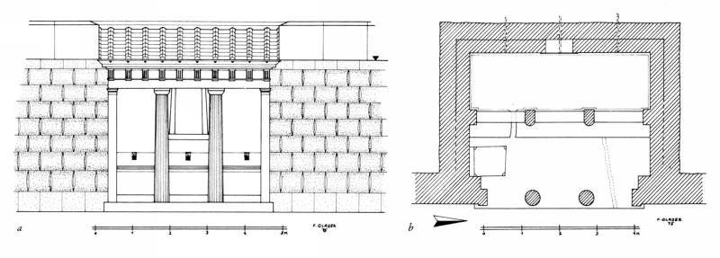
it tastes better. Therefore it seems to be understandable that springs were mythically venerated, especially when they appeared in very dry regions. In general such springs
were framed and a fountain-house had been constructed including a basin in order to enable the drawing of water by people.
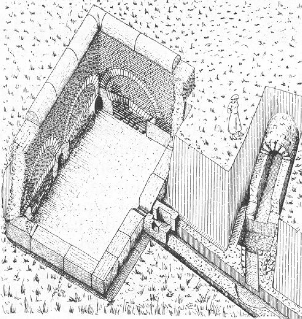
As examples the Gihon-spring in Jerusalem and the Castalia in Delphi may be mentioned. Fig 1 shows such a fountain-house in Sikyon.
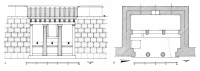 |
fig 1. Drawing of a fountain house (krène) in Sikyon (Greece) |
 |
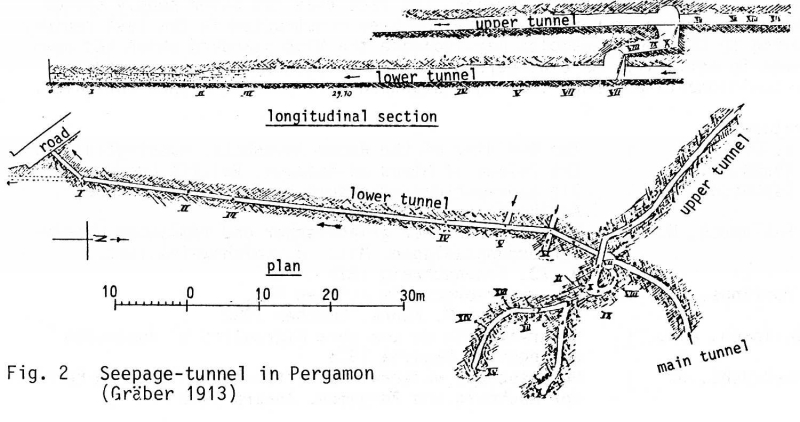
fig 2. Seepage tunnel in Pergamon (Turkey) (Gräber 1913) |
 |
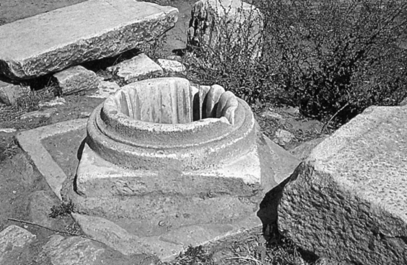
fig 3. Well-top in Aphrodisias (Turkey) |
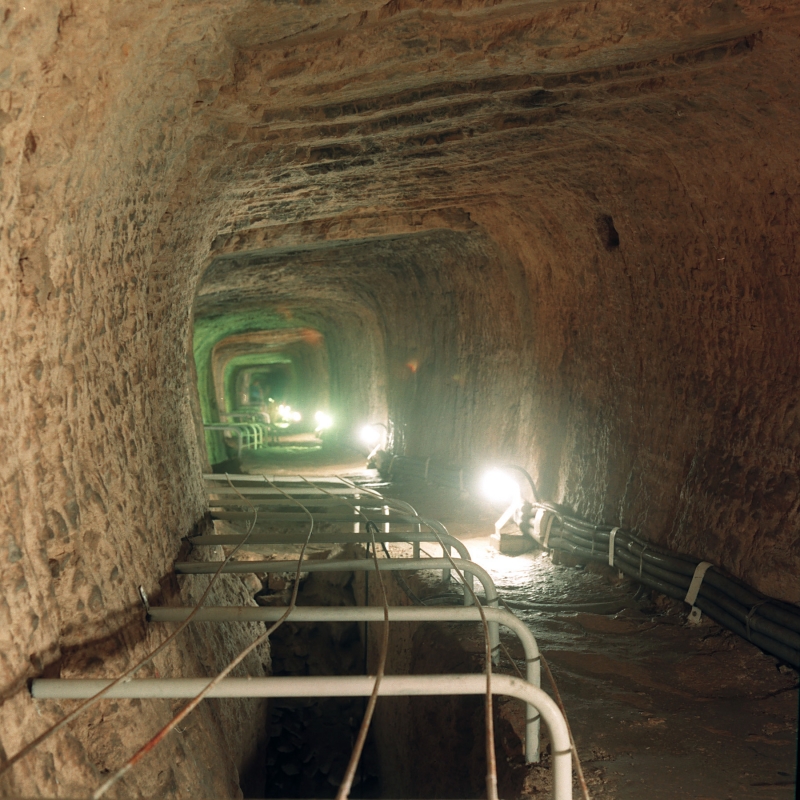
Of course the discharge of springs is limited. Therefore it is not astonishing that people tried to increase it. This for example could be done by seepage galleries, which were
cut into the natural rock. Such a tunnel is described by Graber (1913) for ancient Pergamon. Two tunnels, one above the other, in two different but combined stories
collected the seeping water over a length of more than 150 m and was led into a basin at the surface (Fig. 2). This construction at least functioned until the beginning of this century.
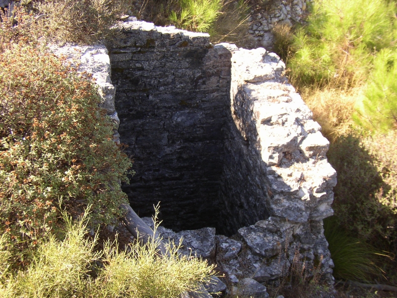
But not always the water necessary rose to the surface in springs. Often wells had to be dug into the soil or rock in order to meet an aquifer. If necessary the wells had
to be strengthened by linings. Kienast (1981) describes the method of undermining the well-rings and thus sinking them. The mouth of a well was covered and provided with a top
in order to facilitate the drawing of water. Fig 3 shows such a well-top in Aphrodisias (Turkey). Sometimes deep flutes are clearly to be seen which have been scratched into the marble
by bucket ropes during many centuries of operation. The importance of wells for the water supply especially in rural regions is underlined by the laws of Solon (640-560 B.C.).
He ordered that public wells could be used by the inhabitants within a radius of four stadions (about 740 m). Anybody who lived in a longer distance should dig a well for himself.
Those people only who had dug more than eleven fathoms (about 11 m) deep without finding water should be allowed to draw a certain amount of water from the well of his
neighbor two times a day (Merckel 1898).
Aspects of defense
Wars happened to be relatively often since early history until the long period of peace in Roman times. People had strategic advantages when defending a settlement or a castle
on top of a hill. Therefore castles, villages or towns often had been founded on isolated mountains since Mycenaean times. The supply with water for human beings and
animals was compulsory also at these places, especially in respect to the probability of being besieged for a long period of time. However springs, wells, rivers,
or lakes are situated at the bottom of hills or in valleys. Therefore people had three possibilities for the water supply:
- Deep wells to be dug into the aquifer
- Cisterns in order to store precipitation
- Transfer of water from springs or subsurface sources
Deep wells
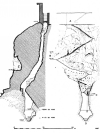 |
fig 4. Deep well under the Acropolis of Athens (Greece) (Kienast 1981) |
As an example for the water supply by means of deep wells the Athenian acropolis may be mentioned. Fig 4 shows the well and its fleet of stairs on which people could walk
down in order to draw water. This well had been constructed in Mycenaean times (Kienast 1981).
Cisterns
The second alternative is the storage of precipitation in cisterns, which are proved having been constructed in the whole region around the Mediterranean and the Near East
since the 3rd Mill. B.C.. E.g. every house in Jerusalem had its own cistern. Very often they were cut pear-shaped into the natural rock with a small inlet being covered by stones
or wooden plates. In Hellenistic and Roman times the number of cisterns built of stones increased. Not seldom the walls had been plastered in order to avoid seepage losses.
Fig. 5 shows a cross-section of a cistern in Humeima / Auara (Jordan).
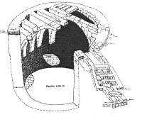 |
fig 5. Model of the other Nabataean cisterns in Humeima / Auara, Jordan. Inside the settlement about 10 other cisterns were present, all but one of circular shape, with capacities up to 200 m3, for private use and built by individual families, according to Oleson (Oleson 1995, SHAJ V pag 712) |
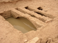 |
fig 6. Nabataean cistern in Humeima / Auara (Jordan) with several of the 16 transverse arches. The cistern is filled with rain water (early April 2007). Total capacity of the basin about 450 m3 |
The cisterns of the acropolis of Pergamon systematically have been surveyed and analyzed by Garbrecht (1969). He also had tried to estimate the population of the
early Hellenistic city from the possible water supply. For his calculation he assumed an average volume of each cistern, the same specific number of the cisterns per ha
inside the whole city as in the upper part, the same climatic situation in antiquity as today, and a water consumption of 10 l/d per person. Under these circumstances
about 20.000 people could have survived a besiege of one year. Thus it was proved that the cisterns were the backbones of the municipal water supply.
Local transfer
Sometimes the water to be stored was not led into cisterns but into open pools. Famous are the pools of Jerusalem which are partly mentioned in the Bible. The realization
of deep wells as well as cisterns was limited locally. The structures could be operated and maintained under the protection of the city walls. Thus the third alternative,
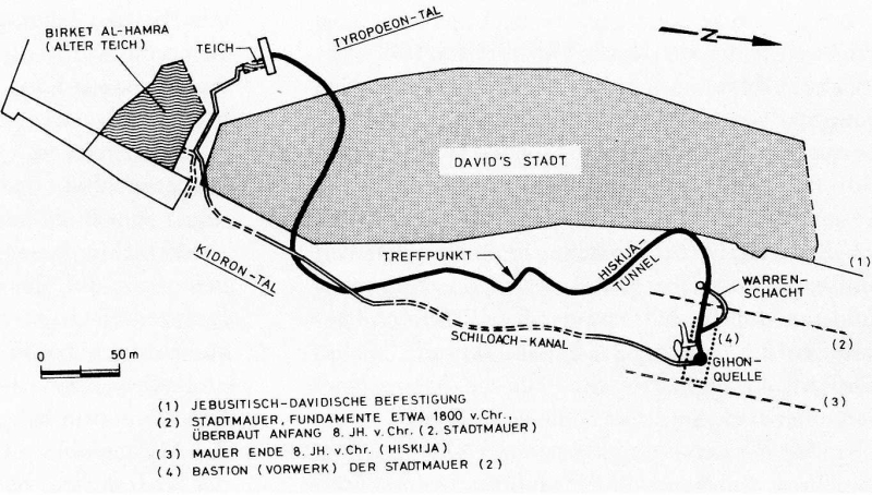
i.e. the local transfer of water from a place outside of the city into it, meant by far an increased effort. As an example again may be referred to Jerusalem. King Hiskia
ordered the construction of a tunnel in order to lead water of the Gihon-spring to the Siloah-pool inside the city. This happened around 700 B.C. during a war against
Assyria and also is mentioned in the Bible. The so-called Hiskia-tunnel is well known. Its total length is about 530 m, although the direct distance between entrance
and outlet amounts only to 370 m. These measures indicate, that the tunnel doesn't run in a straight line. In fact it is S-shaped in plan (Fig. 7). In the tunnel an inscription
has been found informing us that the tunnel had been dug from both sides. As obviously no shaft existed it is still discussed today how the builders knew where they had been underground and how they had to dig in order to meet the other branch.
 |
fig 7. Hiskia tunnel in Jerusalem (Israel) (Kienast 1983) |
The principle of this water deviation was not new. E.g. the so-called Perseia-spring in Mycenae also had been kept underground and its water led to a basin inside the city.
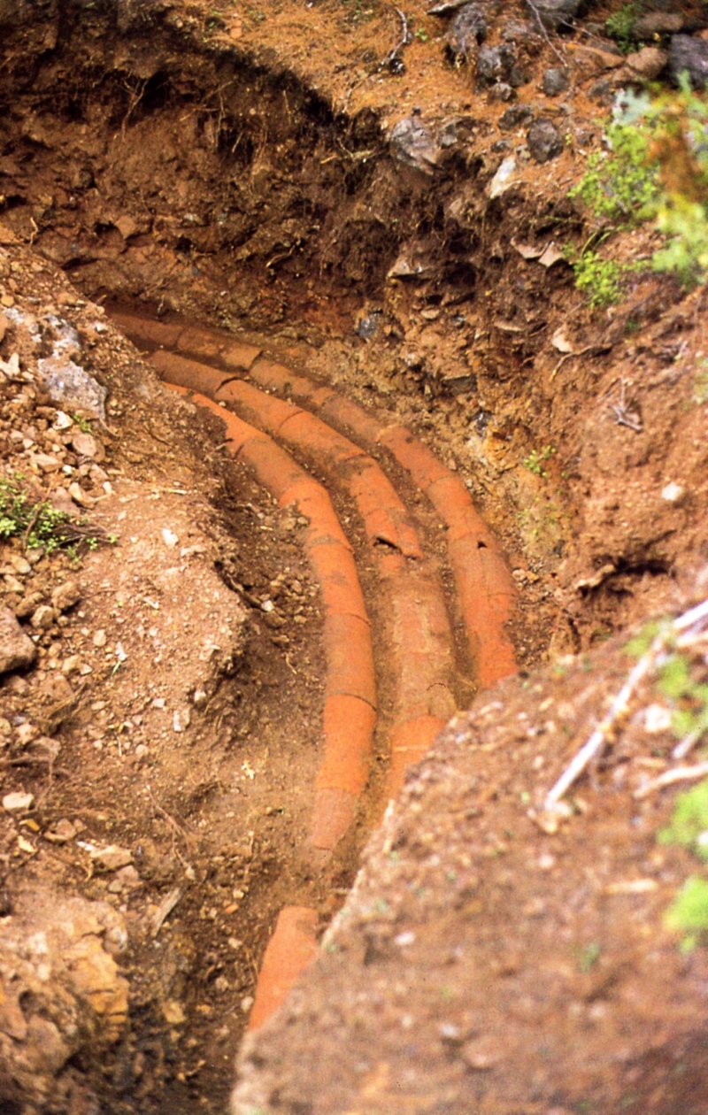
However this basin was cut deep below surface. But from early history another conduit has to be mentioned as example for the local transfer. It is a pipeline for the palace
in Knossos on Crete. As shown by Evans (1930) the water from the Mavrokolybo-spring was led in a conduit of taper-shaped terracotta pipes. However the importance
in respect to science is, that in the course of the pipeline a pressurized part existed, although the pressure was small. The fact that the principle of communicating tubes
was applied in practice can also be proved by a fresco found in the palace. It clearly shows a fountain, which postulates the application of a pressure pipeline.
Thus can be concluded, that in the 2nd millennium B.C. all artificial elements to improve the water supply of settlements had been known and practiced, including the
most difficult one, i.e. pressure conduits. The following development therefore was a technological, not a scientific one.
Developments in Greek Regions
The traditional cultures collapsed in the disturbances of the migrations around the 10th c. B.C. From the following epoch little evidence of hydro-technical structures
has been found. Necropolises indicate that large settlements must have existed, but they are hardly proved. The same is true for water supply systems. In the archaic epoch
powerful city-states developed in Greece. An increased construction performance is evident in this era, also for the water supply. The systems being built had been
of high standard although no technological development from poor to high level could be proved as Kienast (1981) pointed out. Therefore it remains an open question
how far the knowledge and ability in Greece had been inspired from the neighboring regions, especially from Asia Minor and the Near East. The water supply technology
had further been developed with respect to industrialization in the following Classical and Hellenistic epochs. However this development had reached its peak with the
Roman conduits, based on quite different technological achievements. The whole development will roughly be outlined.
Archaic Systems
The Eupalinos-aqueduct of Samos may be presented as an example for an archaic supply system. Today the fountain-house is still in use and gives us an impression
on this kind of element. The water of the spring had been collected in a triangular basin. Silt could deposit here. The basin had been covered. 14 pillars bore the ceiling,
which again had been covered by earth in order to hide it from besiegers during war (Kienast 1979). The water flew from the basin into a pipeline (inner diameter 25,5 cm)
which was placed in a tunnel. Like many other archaic tunnels this most probably was a protection structure for the pipelines. The tunnel had been constructed like many
others in a so-called qanat-method: from shafts, dug vertically into the rock, the tunnel had been cut horizontally to two sides. The length of this qanat-type tunnel is about 890 m.
Then the famous Eupalinos-tunnel followed which is mentioned by Herodot (about 450 B.C.). This structure of 1040 m length is cut through the city mountain from two sides,
i.e. from the north and the south. The southern branch runs straight while the northern one shows some bends in its course. A convincing explanation for these bends
has not been presented yet. But it is evident, that Eupalinos knew always the position underground. Kienast (1979) identified 5 different longitudinal and 5 different horizontal
measurement systems in the tunnel. Due to these measurements it was possible that both branches met in the middle. In the tunnel then another trench had been dug
which changed into a separate tunnel in the southern part. In this trench respectively tunnel the pipeline had been installed. The whole system obviously was in operation
for more than 1000 years. Fig.8 shows a cross-section of this structure.
 |
fig 8. Eupalinos tunnel on the island of Samos (Greece) (550 B.C.). Three to eight meters under the main tunnel a second, smaller one was hewn for the terracotta pipeline -
© T. Bolhoj |
 |
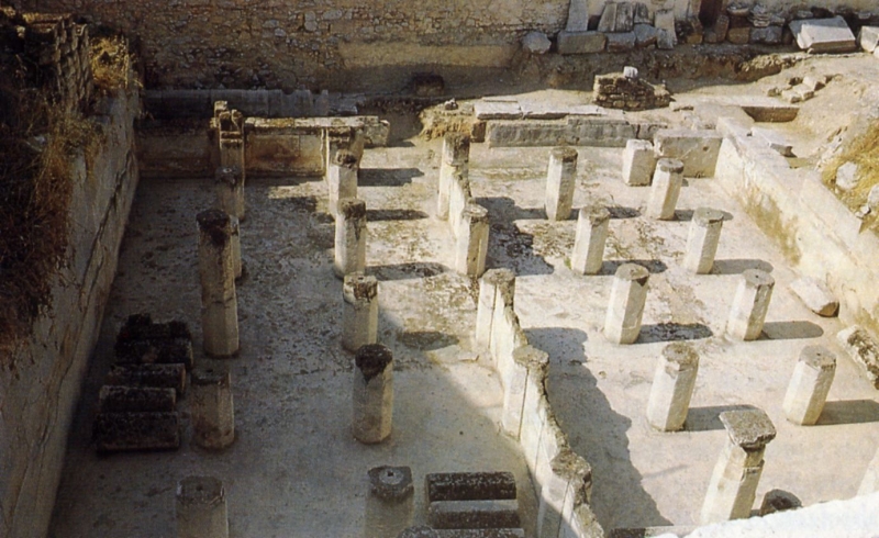
fig 9. An excavated Greek double reservoir at Megara (Greece), notable for its use of pozzolanic mortar - a lime based mortar made with
an additive of volcanic ash that allows it to be hardened underwater. Its total volume was about 250 m3 which was remarkable in those days in late archaic times. |
The water supply system of Megara may be mentioned as an example of a conduit with a storage basin at its end. Two terracotta pipe-lines led ground- and springwater
to a double reservoir of an area of 13,7 m x 17,9 m. In front of it and connected to it was another basin in order to draw the water from here. The ceiling of the reservoir
had been born by 35 columns. The basin was thought of being that one mentioned by Pausanias (about 170 B.C.), the so-called fountain-house of Theagenes
(7th c B.C.). But Gruben (1964) proved, that it was younger. Anyhow the reservoir could store the discharge for daily regulations (fig 9).
Hellenistic Systems
The technique for aqueducts had been improved in Classical and Hellenistic times. Costly tunnels in order to protect the pipelines were omitted. The single pipes were formed
more advantageous with respect to their expenditure. After all this resulted from the steady increase of water demand because of the sharply increasing population.
The demand was mainly covered by local transfer, i.e. by aqueducts. This may be shown at the acropolis of Pergamon.
 |
fig 10. Terracotta pipes, part of the Madradag aqueduct of Pergamon (Turkey) |
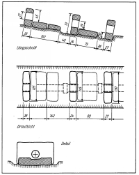 |
fig 11. Drawing of the foundations of the pressure pipes of the Madradag siphon of Pergamin (Turkey) |
The first pipe-line of Pergamon had been constructed most probably in the era of Attalos I (241-197 B.C.). It was a single conduit. The pipes showed an inner diameter of 13 cm.
The course was more than 20 km long. Near the acropolis a pressure-line was necessary with a pressure of 2 to 3 bar. Few years later a double pipeline
had been constructed in mainly the same line but on a slightly higher level. Therefore also a pressure-line was necessary north of the acropolis. The inner diameter of the pipes
measured 18 cm. The possible discharge of the second conduit was nearly 4 times as big as the first one. Again only few years later the third aqueduct had then been
constructed, probably under the reighn of Eumenes II (197 - 159 B.C.). It was a triple pipeline from the Madrdag mountains in the north with a length of nearly 50 km. (fig 10).
However the most important part was the pressure-line at its end having a length of 3,2 km. The maximum static pressure amounted to about 19 bar. The pressure-pipes
had been of cast lead. According to Garbrecht (1978) the conduit had ended in between the palaces. The water then run to the main cistern. The overflow from there
was led downhill from one cistern to the others so nothing of the valuable liquid was wasted. Thus the cisterns changed their task from a reservoir of caught precipitation
into storage of continuously flowing water. The discharge of the total hitherto water supply system of the acropolis consisting of the cisterns, the single and the
double pipeline was doubled when the Madradag-conduit started operation. This aqueduct is proved having been operated for several hundred years. It is looked upon
as peak of Hellenistic water supply technology.
Developments in the Roman Empire
In general the Greek conduits have been installed subsurface as far as it is known from literature. For sure this was done because of safety reasons. Otherwise
a visible conduit would have been cut by any besieger of a city. This had been changed in the Eastern Mediterranean not before Roman times, when Roman technology
dominated in this region. It was developed in Italy obviously by the Etruscans. They used channels for irrigation and water supply and their knowledge was inherited
by the Romans. Thus it is not surprising that in 312 B.C. the first aqueduct for the city of Rome, the so- called Aqua Appia, was constructed as a channel. For this
and the subsequent one, the so called Aqua Anio Vetus, it was still imperative being constructed underground. It was done in the qanat-method, described already
for the first part of the Eupalinos conduit of Samos. Eventually, after the final destruction of its main enemy, Carthage, people of Rome dared to construct a channel having
a long section above surface, i.e. the Aqua Marcia. In the following time such sections, especially arcades across valleys, became part and more or less symbol of almost
all Roman aqueducts. This technology spread over the whole Roman Empire in the long period of peace, the Pax Romana.
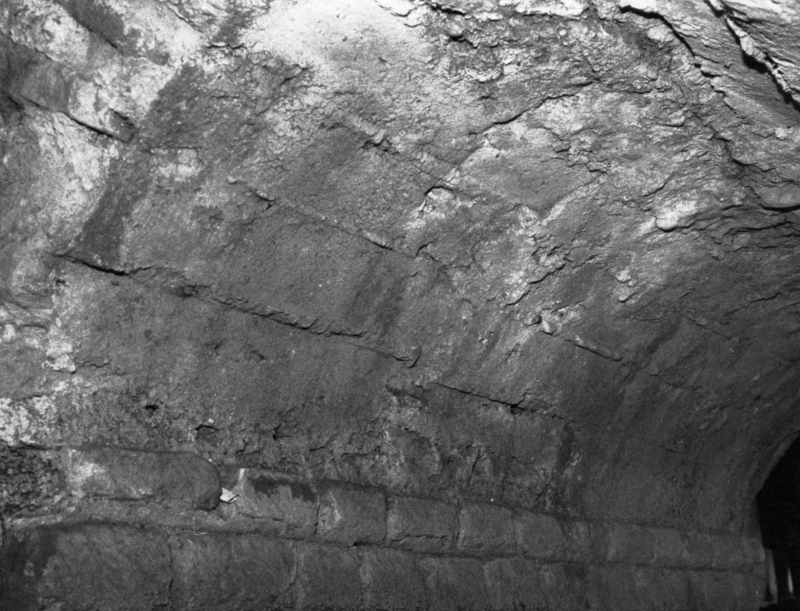
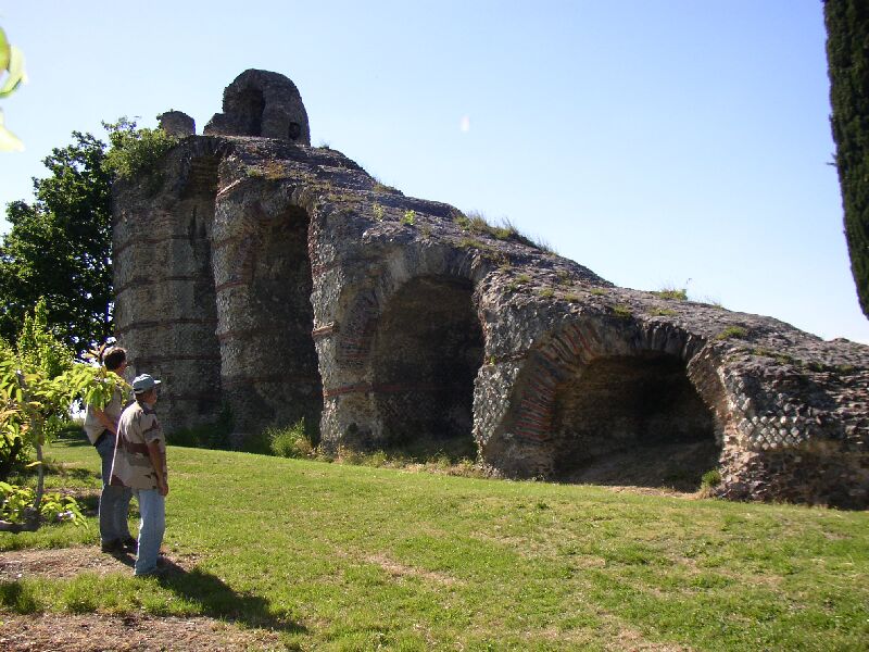
Adits
Water was caught for many Roman channels in seepage galleries or fountain-houses like for Greek conduits. Both elements are proved for the Eiffel-channel of Cologne.
Fig 12 shows the so called Klausbrunnen, which has been restored by Haberey (1972). Water could flow into the basin through 10 slots in the walls. Due to the big cross-section
in the basin the water moved slowly. Therefore any silt could deposit. Then the water discharged into the channel to Cologne. A weir could interrupt the outflow of the basin.
The restored structure can still be visited today.
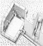 |
fig 12. Klausbrunnen, a collection basin, one of the sources of the aqueduct of Köln (Cologne), near Kallmuth (Germany) |
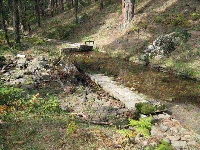 |
fig 13. A river take-off, the start of the aqueduct of Segovia (Spain) |
 |
fig 14. The Cornalvo dam, the main feeders for one of the aqueducts of Merida (Spain) |
 |
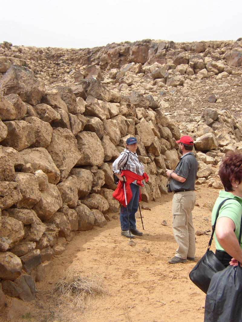
fig 15. An ancient wadi-dam (3000 B.C.) in Jawa (N-Jordan) |
Contrary to the Greek the Romans used surface water from rivers or lakes also. River diversions had been constructed e. g. for the aqueducts of Side, Trier,
Aix-en-Provence, Rome, etc. Like today weirs had been built in antiquity as diversion structure. A trash rack was probably applied at the channel inlet in order to prevent
floats moving into it. Fig 13 shows such a diversion structure at the beginning of the channel for Segovia (Spain).
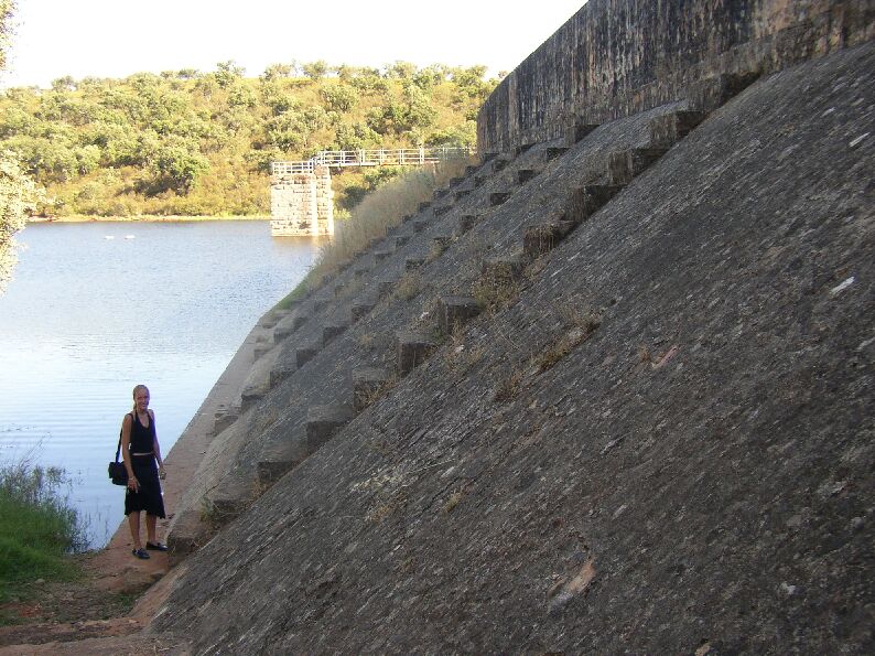
The diversion of water from a dam is already mentioned by Frontinus (around 100 A.D.). He reports that the Emporer Trajan ordered the transfer of the diversion for the
Aqua Anio Novus from the Anio-river to the dam in the Anio-valley near the town Subiaco. As Frontinus wrote, now pure water was discharged to Rom in this channel.
The dam has been destroyed in 1305 A.D. No remains of it have survived till today. However the diversion of water from a dam can still be seen in Merida in Spain (Fig.14)
As intake of the Cornalvo-dam a tower is erected as it will be constructed for earth dams today. Fig 15 shows one of several dams in de wadi near Jawa (N-Jordan)
to collect the water.
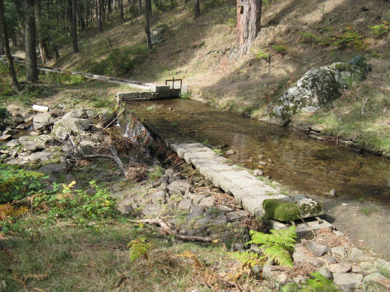
Dams as temporary transfer of the water supply had been constructed normally at the beginning of channels. However the pools of Salomon in the course of the
aqueducts of Jerusalem show that even in the middle of a line a storage basin could be located. The three famous pools, which are dated in the Hasmonean period,
not to the time of Salomon (about 10 th cent. B.C.) as could be assumed by its name.
Channels
Behind the adit normally followed a channel as duct for the water. Three different principles seem to have been developed for the determination of its cross-section:
- Provision of a sufficient area for the discharge
- Adherence of a nearly constant cross-section along the whole length of the channel
- Access and inspection of the channel from inside
The early aqueducts seem mostly beefing constructed by roughly cut stones set into loam (v. Deman 1934). Parts of the cross-section of the third aqueduct of Rome,
the Aqua Marcia, were built with carefully smoothed square stones. The newly developed limestone-concrete, the so-called Opus Caementitium, and the mortar-technology
prevailed at the construction of aqueducts in Caesarean times. At the aqueduct of Aix-en-Provence (France) and Köln (Germany; fig 16) the impressions of the formwork are still to be seen at the walls. Obviously it had been constructed of poured concrete, as we do it today. The early channels had been covered by slabs which laid across the walls horizontally or gabled. Later the vault prevailed which was either poured over a scantling or being constructed over brick-slabs as lost form.
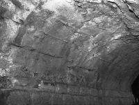 |
fig 16. Prints of formwork in a section of the channel of the Köln (Cologne) aqueduct (Germany) |
 |
fig 17. Manhole (puteus) above the Eupalinos aqueduct on Samos (Greece), made during construction work of the underground channel, later is use for inspection and repairs |
The channels had been impermeable. This was obtained by several different layers of plaster. They prevented cracks because of drying shrinkage or different temperatures
(Malinowski 1978). We have to admire the results of Roman plaster-technology in constructing impermeable channels over long distances.
The slope of the channels depended on the topographical circumstances. If the difference between source and terminal of the aqueduct was small, the slope had to be minimized.
This resulted in slopes of e.g. 0,11 o/oo in a deviation-section for the Kaikos-aqueduct of Pergamon. These figures can only be looked upon as masterpiece of leveling.
Bridges
The bridges of Roman aqueducts became very famous. According to Hecht (1979) they can be distinguished into walls (substructio) and arched bridges (arcuatura).
Walls had been constructed in case the channel level was only a few meters above surface. Arched bridges had been preferred if this height was more than 4 m to 5 m.
The diameter of the arches and the pier width depended on the construction type (concrete, square stones) and the material available. A development from stone setting
to concrete application can be shown for the construction of bridges as it was done already for the channels. The channel on top of the bridge had often been constructed
in the same way as in its normal course below surface.
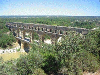 |
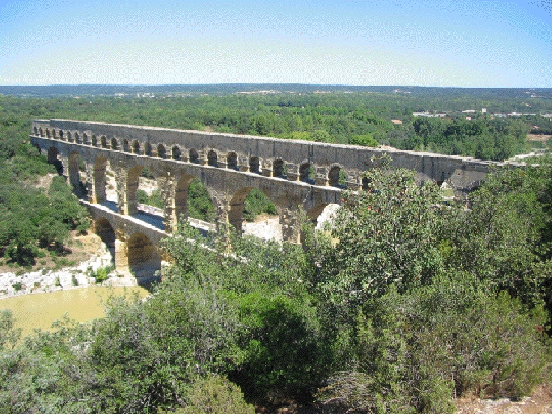
fig 18. The well-known impressive bridge Pont du Gard of the aqueduct of Nîmes (France) |
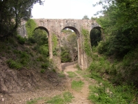 |
fig 19. The Bouteillière aqueduct bridge, north of Fréjus (France) |
High bridges had been built in more than one story. Criteria couldn't be proved for the dependency of the number of stories from the structure height. The famous
Pont du Gard (Fig 18) has three stories at a height of 49 m, however the St. Antonin-bridge of the Aqua Anio Novus of Rome showed 4 arches above each other
at a total height of 35 m only. The local particularities will have determined the layout of a bridge as individual structure like today.
Pressure-conduits
In case valleys to be crossed were very deep pressure pipelines had been constructed also in Roman tié. The principles of the constructions looked like the Greek ones.
The free flow aqueduct terminated in a transition basin (header tank), which the pressure-conduit was connected to. This went downhill into the valley and rose on
the opposite site again. There it terminated again in a transition basin (receiving tank) to the following open channel. The difference to its Greek forerunners was the bridge,
which often bore the pipeline in the bottom of the valley. According to Vitruvius (about 20 B.C.) the line should be kept here horizontally as long as possible. This could be achieved
by a bridge. Remains of these substructures are known from many places of the Roman Empire.
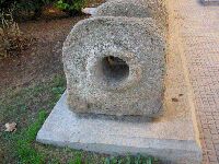 |
fig 20. Pressureline of the aqueduct of Gades / Cadiz (Spain) |
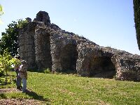 |
fig 21. Headertank (left) and ramp to support the (9) lead pipes which crossed the Yzeron valley. Plat de l'Air, Gier aqueduct of Lyon (France) |
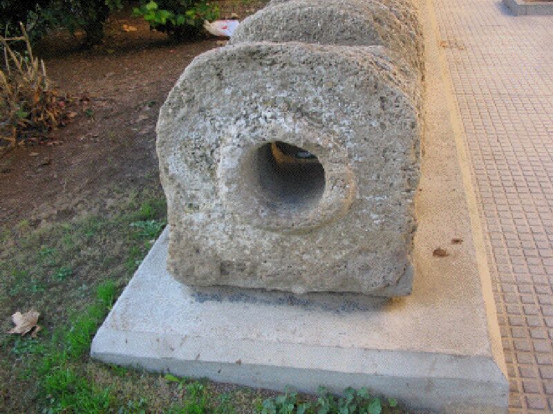
The pipes had been manufactured from different materials. Very often lead or stone pipes had been used. However terracotta pipes covered by concrete are also known, e.g.
from Almunecar (Spain). Lead pipes had been no longer cast, but manufactured from a plate, which had been bent around a cylinder and then soldered at the joint.
Thus the width of the wall could be reduced. According to the measures and weights given by Vitruvius the minimum width should be about 6 mm. The sizes of the pipes
had been standardized. A first series of standard measures is given by Vitruvius, a second one by Frontinus (Fahlbusch 1982). The use of stone pipes is known from many cities.
Fig 20 shows parts of a pipeline still in situ of the aqueduct of Cadiz / Gades in Spain. A similar one can be found near Bethlehem, part of one of the aqueducts of Jerusalem. The single pipes showed male and female sockets. Their joints had often been sealed by a mixture of liétone and oil.
Terminal storage
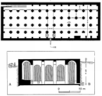 |
fig 22. Plan of the Piscina Mirabilis (12.600 m3), one of the largest ancient water reservoirs in Italy |
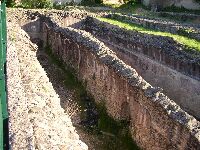 |
fig 23. Two of the four chambers of one of the cisterns (storage basins) on the La Fourvière hill in Lyon (France) |
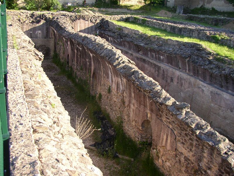
Water discharged continuously into the cities. In order to avoid any waste not seldom a big cistern had been constructed at the end of an aqueduct, e.g. at Lyon,
Pergamon, Carthage, Rome etc. Here the so called Piscina Mirabilis at the end of the aqueduct around the gulf of Naples may be presented. The volume of this cistern
with 5 longitudinal and 13 cross-naves amounted to 12.600 m3. The sinter-crust at the floor, piers and walls proved the long operation for the navy at Cape Misenum (Fig 22).
Water Distribution
In his two books "De Aquaductu Urbis Romae" S.J. Frontinus describes among other items the distribution of water inside the city of Rome. However nearly nothing of this system
has been found in the Italian capital. Archaeological evident is known from other cities. The aqueduct terminated in a distribution structure, a so-called castellum. Fig 24. shows
the respective one that was found in nîmes (France). 13 low-pressure pipelines had been connected to the basin. Most probably they supplied the different parts of the ancient city
and not different customers.
 |
fig 24. The water distribution basin, the Castellum Divisorium of Nîmes (France) |
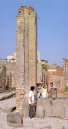 |
fig 25. One of the many pressure reduction and distribution facilities with well annex in Pompeii (Italy) |
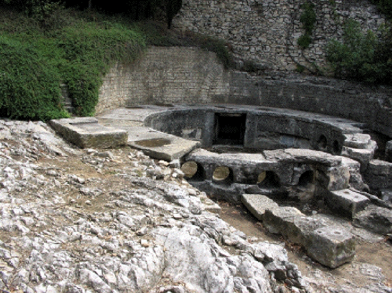
A number of draw-wells along a course of such a main urban pipeline had to be filled up. In order to avoid the waste of water and to supply also other customers distribution towers
had been applied as we learned from the excavations of Pompeii. Fig 25. shows such a tower plus well. About 40 wells also provided the population in Pompeii as far as it is excavated
today. According to Eschebach (1979) people seldom had to walk longer than 50 m to get water. How many cities of today would be glad, if they had such a splendid water supply
and distribution system.
Conclusion
As was outlined the different methods of improving the water supply of settlements have been invented very early. Basically no element has been added up today.
However the technological skill has been improved steadily that world records in some fields have been achieved in antiquity for many, many centuries. The water supply
of some ancient cities amounted up to several hundred liters per day and person, a number which today is provided for cities only in a few highly industrialized countries.
The fact that the water supply system for many big cities in Central Europe had been constructed in the last century following to the Roman examples may indicate the
high standard, which had been achieved in antiquity. As engineers of the 20th century we only can admire these achievements and hope that this standard will soon
be gained worldwide.
Literature
- Deman, E. van: The Building of the Roman Aqueducts. Washington 1934
- Evans, E. : The Palace of Minos at Knossos. Vol.III London 1930
- Eschebach, H. : Die Gebrauchswasserversorgung des antiken Pompeii. Antike Welt, 2 1979
- Fahlbusch, H : Vergleich antiker griechischer and romischer Wasserversorgungsanlagen. Mitt. d. Leichtweiss-Inst. H. 73 Braunschweig 1982
- Frontinus, S.J. : Wasserversorgung im antiken Rom. Deutsch von G. Kuhne. Munchen 1982
- Gallardop, A.R. : Supervivencia de una obra Hidraulica el Aqueducto de Segovia. Segovia 1975
- Garbrecht, G. Untersuchung wasserwirtschaftlicher Anlagen im Bereich der Hochburg von Pergamon. Ankara 1969
- Garbrecht, G. : Wasserwirtschaftliche Anlagen des antiken Pergamon. Die Druckleitung. In: Mitt.d. Leichtweiss-Inst., H. 60. Braunschweig 1978
- Gräber, F. : Altertumer von Pergamon, Bd.I,3. Die Wasserleitungen. Berlin 1913
- Gruben, G. Das Quellhaus von Megara. Deltion, 19 (1964)
- Haberey, W. Die römischen Wasserleitungen nach Ko1n. Bonn 1972
- Hecht, K. Baugeschichtliche Betrachtungen zu einigen Aquadukten der Kaikos-Leitung von Pergamon. In: Mitt. d. Leichtweiss-Inst., H.64. Braunschweig 1979
- Herodot : Histories. Hrsg. Farber, H. and Faltner M., Vollmer Verlag Wiesbaden
- Kienast, H. : Der Wasserleitungsstollen des Eupalinos auf Samos. In: Mitt. d. Leichtweiss-Inst., H.61. Braunschweig 1979
- Kienast, H. : Bauelemente griechischer Wasserleitungen. In: Mitt. des Leichtweiss-Inst., H.71. Braunschweig 1981
- Malinowski, R. : Einige Baustoffprobleme bei antiken Aquadukten. In: Mitt. des Leichtweiss-Inst., H.64, Braunschweig 1979
- Merckel, C. Die Ingenieurtechnik im Altertum. Berlin 1899
- Pausanias : Description of Greece. Vol. I, London 1966
- Vitruvius, M. : Zehn Bücher über Architektur. Deutsch von Fensterbusch. Darmstadt 1964
|