See also Roman Groma (Gary A. Robbins).
Often we forget the 'ordinary' instruments like the actus (?; measuring string) and the decempeda (the 10 feet wooden measuring rod).
Tools for Leveling
The nature of Roman tools can be determined both from carved representations of artisans at work, and from actual artefacts that have been preserved to this day (O'Conner, 1993: 45). While examples of the hammer, anvil, axe, adze, pick, knife, scythe, spokeshave, plane, chisel, drill, chorabates, dioptra and file have been found, it is certain that some tools and techniques have been lost.Roman architects were skilled in this kind of work, for which they used sophisticated tools. Besides the ordinary level, similar to the one used today by carpenters, they used devices such as the chorobates and dioptra.
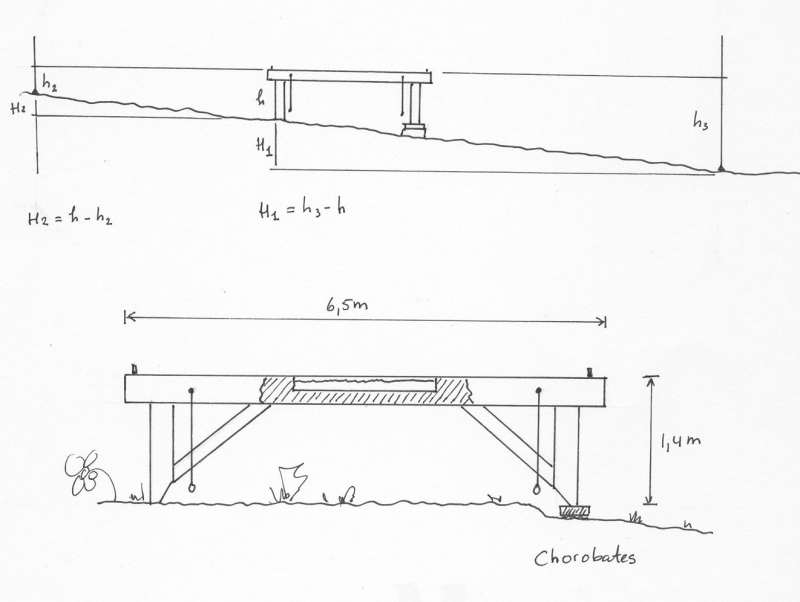
The chorobates was a bench with weighted strings on its sides for measuring the ground's angle on a system of notches, and a short channel in the centre, likely for testing the direction of the water flow (O'Conner, 1993: 45). It was mostly used for the levelling of aqueducts. It was probably too unwieldy for general levelling (Dilke 1971:76). It was also probably too unwieldy to use in the construction of tunnels, being too big to manoeuvre easily in confined spaces. See the illustration of a chorobates.
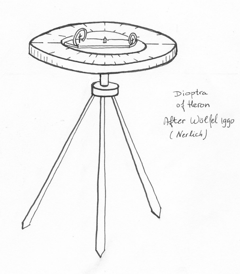
The dioptra was a different kind of level. It rested on the ground, and was finely adjusted by tilting and rotating the top part by means of precision screws, it could assess the angle of a stretch of aqueduct by looking through pivoting sights (O'Conner 1993: 45). See the illustration of a dioptra. Whether or not it was actually used is debatable, as only Hero of Alexandria - he liverd during Nero's reign - gives us a description of the devise. Vitruvius recommends the dioptra as an alternative for levelling water-courses and Pliny the Elder recognised its efficiency for astronomical work. Vitruvius' reservations and the lack of further written evidence suggests that it may have been regarded as too elaborate, expensive and unwieldy for general use (Dilke, 1971:79). As Hauck (1988:44) points out, the dioptra was essentially a forerunner of the modern theodolite. Despite its apparent complexity, it would have been useful in tunnels where the chorobates could not be used.
However, a reading of Vitruvius leaves the impression that the dioptra may have been the first choice in some cases. While his reliability has been questioned, it seems a stretch that that he would not have knowledge of what would be a common tool. In Vitruvius' own words (8.5.1):
The first stage is to fix levels. This is done by dioptrae, or water levels, or the chorobates. But the more accurate method is by the chorobates because the dioptrae and he water levels mislead.If the chorobates is superior, why would the other devices be used? Vitruvius provides the answer; wind can disturb the plummets on the chorobates (8.5.2), a problem to which the dioptra and water levels would have been immune.
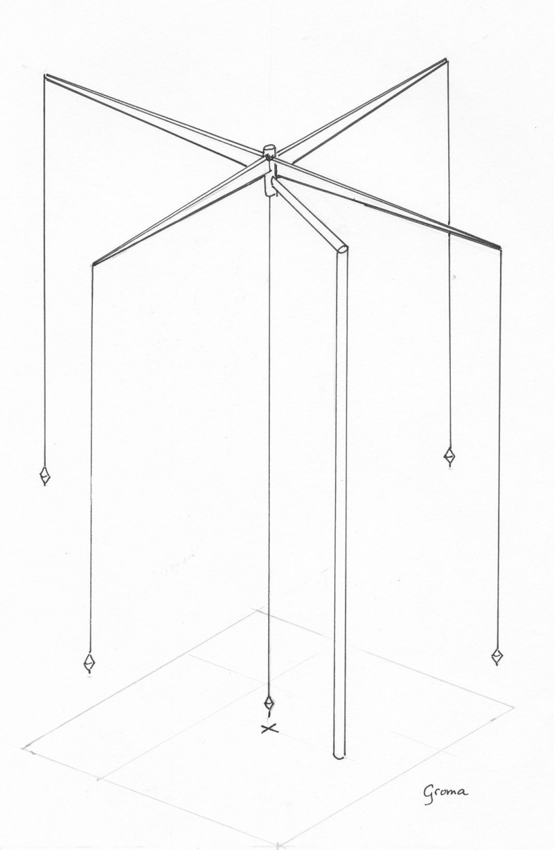
The principal Roman surveying instrument was the groma. It was regarded as the tool most typical of a surveyor; it appeared in stylised form on the tomb of Lucius Aebutius Faustus. L. Aebutius Faustus lived in the colony of Eporedia in northern Italy. He was a freedman (Hauck, 1988:42). The groma was used in military and civilian surveying, and we are told that a central point in a military camp was called the gromae locus (Dilke, 1971:66). Since no groma has survived completely intact, we do not have an accurate picture of one. The one that appears on Lucius Aebutius Faustus' tomb serves as a starting point (see illustration of the tombstone of Lucius Aebutius Faustus). The staff of the surveying instrument is upright and the cross is detached and laid diagonally across it. There is not enough evidence to say for certain that this instrument is a groma, but the consensus is that it most likely is (Dilke, 1971:66). It certainly matches the description.
During excavations in Pompeii in 1912, some metal parts were found in Verus the surveyor's workshop that might be the remains of a groma. Matteo Della Corte created a plausible reconstruction from these remains. At the top is the cross, which has iron sheeting and originally enclosed wooden arms. To prevent inaccuracy due to the wearing away of the wood, the arms were reinforced near the centre by bronze angle-brackets. A plumbline hung through a hole near the end of each arm. The four plumbbobs were not identical, but came in two pairs arranged at opposite corners. The system of sighting from one plummet to its opposite number worked most effectively when the cross was off-centre, otherwise there would be an obstruction. The cross was thus placed on a bracket and not directly on the staff. The bottom of the bracket fitted into a bronze collar set into the top of wooden staff. The horizontal distance of the centre of the cross from the staff was 23.5cm. The staff may have been as long as 2m (Dilke, 1971:70).
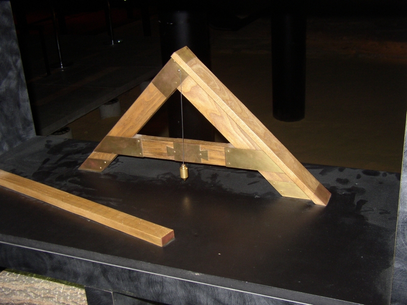 |
| Reconstruction of a libella in the 'Pont du Gard-museum', 2 km west of Remoulin (France) |
A portable sundial was also found in Verus' workshop in Pompeii. Not only was this intended to indicate time, but lines on two of the sides were used for measurements. The exact use of the sundial is uncertain (Dilke, 1971:72). A sundial can be used for more than tracking time, it can also be used to orientate buildings.
Another levelling instrument used by the Romans was the simple libella. It consisted of a frame in the shape of the letter A, with the addition of a horizontal bar on top. From the apex a plumbline was suspended that coincided with a mark on the lower crossbar when the instrument was level. Other marks could have been added to indicate other slopes, but there is no evidence that this was done (Hauck, 1988:43).
The horizontal accuracy of the aqueducts speaks of the quality of the tools and skill of the Roman engineers. The tools, however, seemed less accurate when used for turning angles. For example, when building an aqueduct at Saldae a tunnel had to be dug through a mountain. The Romans had teams digging on each side of the mountain, but when each half of the tunnel exceeded half the thickness of the mountain, they realised they had a problem. Nonius Datus was an army engineer and summoned to Saldae. On his way he was robbed and wounded by bandits. In compensation for his perseverance and skill, he was awarded with a monument (see illustration) at Lambaesis. He discovered that both teams had veered to the right and missed each other. The error was lateral and not vertical, probably the more common of the two possible errors (and also the easiest to correct).
From Evan J. Dembskeys thesis